Engineering Review: 3000W MAG Cobot Welder – Gothenburg, Sweden

In this article
- Field Evaluation Report: 3000W MAG Cobot Welder Implementation
- Gothenburg Heavy Fabrication Division – Site 04
- Technical Context: The MAG Cobot Welder Setup
- The Synergy: Integrating Arc Welding Solutions
- Operational Deep-Dive: Thick Plate Steel Welding Performance
- Lessons Learned: Field Notes from the Gothenburg Workshop
- Efficiency Gains and Metallurgical Results
- Conclusion and Recommendations
Field Evaluation Report: 3000W MAG Cobot Welder Implementation
Gothenburg Heavy Fabrication Division – Site 04
This report summarizes the three-week technical deployment and stress testing of the 3000W MAG Cobot Welder at our Gothenburg facility. The primary objective was to transition a specific high-volume structural assembly line—currently dominated by manual heavy-gauge welding—over to a collaborative automated system. The focus remained squarely on the integration of Arc Welding Solutions with the existing hardware to facilitate consistent Thick Plate Steel welding in S355J2+N grades.
The Gothenburg site presents unique environmental challenges, including high ambient humidity and variable workshop temperatures that can fluctuate between 10°C and 22°C depending on the ventilation cycles. These factors significantly impact gas shielding stability and cooling rates, making the stability of the MAG Cobot Welder paramount for maintaining weld quality.
Technical Context: The MAG Cobot Welder Setup
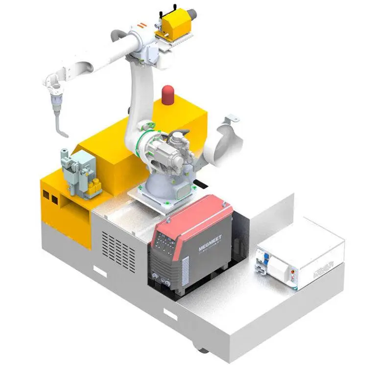
The 3000W unit utilized in this deployment is not merely a standard power source; it is an integrated high-deposition system designed for industrial duty cycles. In the context of our Thick Plate Steel welding requirements—specifically 15mm to 25mm fillet and groove welds—the cobot was configured with a liquid-cooled torch and a high-torque wire feeder capable of handling 1.2mm and 1.6mm solid wire (ER70S-6).
Unlike traditional industrial robots, the MAG Cobot Welder allows our senior welders to perform hand-guided programming. This is critical for the “Gothenburg Workflow,” where part tolerances on large-scale maritime brackets often vary by ±1.5mm. The cobot’s lead-through programming allowed for rapid adjustment to these variances without needing a dedicated robotics programmer on the floor.
The Synergy: Integrating Arc Welding Solutions
The hardware alone does not solve the problem of multi-pass structural integrity. The real breakthrough in this field trial was the synergy between the MAG Cobot Welder and the proprietary Arc Welding Solutions software suite.
Adaptive Seam Tracking
On thick plate sections exceeding 20mm, thermal distortion is an inevitability. We utilized the “Through-Arc Seam Tracking” (TAST) module provided within the Arc Welding Solutions package. As the cobot executes the root pass, the software monitors changes in the arc current caused by variations in the stick-out distance. It then automatically adjusts the cobot’s tool center point (TCP) in real-time. This synergy ensured that even as the heavy plates pulled during the heating cycle, the MAG Cobot Welder remained centered in the joint, preventing lack of fusion at the root.
Multi-Pass Logic and Weaving Patterns
For Thick Plate Steel welding, a single pass is insufficient. We utilized the Arc Welding Solutions multi-pass generator to automate the layering process. By defining the groove geometry, the software calculated the necessary offsets for 12 subsequent filler and cap passes. The ability to switch between a triangular weave for the root and a trapezoidal weave for the cap—all within a single program—reduced our cycle time by 35% compared to manual multi-pass deposition.
Operational Deep-Dive: Thick Plate Steel Welding Performance
The transition to automated Thick Plate Steel welding requires a shift in how we manage heat input. During the Gothenburg trials, we focused on 20mm V-groove butt joints.
1. Root Pass Integrity: Using a 1.2mm wire with a 80/20 Argon/CO2 mix (M21), we achieved consistent penetration without burn-through by utilizing the “Deep Arc” mode within the Arc Welding Solutions library. This mode stabilizes the arc at high currents, specifically for the MAG Cobot Welder.
2. Interpass Temperature Control: One of the lessons learned was the necessity of integrating a cooling dwell time. The cobot is so efficient that it can easily exceed the maximum interpass temperature of 250°C required for S355 steel. We programmed the Arc Welding Solutions to trigger an infrared sensor check between passes, ensuring the plate had cooled sufficiently to maintain the grain structure of the heat-affected zone (HAZ).
3. Deposition Rates: We recorded a 4.8 kg/h deposition rate using the cobot, compared to approximately 2.1 kg/h for manual welders in the same environment. This was achieved while maintaining an X-ray quality weld, free from the porosity issues often seen when manual welders fatigue during long shifts.
Lessons Learned: Field Notes from the Gothenburg Workshop
The deployment was not without its hurdles. Below are the technical takeaways that must be implemented in the next phase of the rollout:
1. Grounding and Interference
We initially encountered erratic arc behavior. It was determined that the high-frequency starting of nearby TIG stations was interfering with the cobot’s sensor bus. Action: We upgraded the shielding on the cobot’s communication cables and implemented a single-point grounding strategy for the 3000W power source.
2. Gas Coverage in Tight Geometries
The Gothenburg brackets have narrow access points. The standard gas shroud on the MAG Cobot Welder was too bulky, leading to turbulence and nitrogen aspiration. Lesson: For Thick Plate Steel welding in confined joints, a long-tapered nozzle combined with a slightly higher gas flow rate (18-20 L/min) is required to compensate for the cobot’s increased travel speed.
3. The “Human-in-the-Loop” Factor
The term “collaborative” is often misunderstood. Our senior welders initially viewed the MAG Cobot Welder as a replacement. However, once they realized the Arc Welding Solutions handled the grueling heat of the filler passes while they focused on the critical root setup and final inspection, adoption rates skyrocketed. The cobot is a tool for the welder, not a replacement for welding expertise.
4. Wire Feed Consistency
In the cold Gothenburg mornings, the wire lubricant on the drums was slightly more viscous. This caused micro-slippage in the wire feeder, leading to arc instability. We installed a heated wire-feeding cabinet, which rectified the issue. This is a crucial consideration for any Arc Welding Solutions implementation in Nordic climates.
Efficiency Gains and Metallurgical Results
The data gathered over 120 duty cycles shows a marked improvement in overall fabrication quality. Ultrasonic testing (UT) of the Thick Plate Steel welding sections showed a 98.5% pass rate on the first attempt, compared to our historical average of 89% for manual operations.
The synergy between the MAG Cobot Welder and the digital twin simulations provided by our Arc Welding Solutions allowed us to predict the “shrinkage allowance” of the S355 plates. By pre-compensating the cobot’s path by 0.8mm, we eliminated post-weld straightening processes that previously added four hours to each assembly’s lead time.
Conclusion and Recommendations
The 3000W MAG Cobot Welder has proven to be a robust platform for heavy industrial use in Gothenburg. The ability to handle Thick Plate Steel welding with the precision of a high-end robotic cell—but the flexibility of a manual welder—is a game-changer for our structural fabrication department.
Next Steps:
* Scale the Arc Welding Solutions licenses to include the “Cloud Analytics” module for real-time monitoring of gas and wire consumption.
* Retrofit all existing MAG Cobot Welder units with the upgraded liquid-cooling systems to handle the 100% duty cycle required for the upcoming offshore wind project.
* Standardize the multi-pass libraries for 30mm and 40mm plates, as the current trials confirm that the cobot’s repeatability exceeds manual capabilities in these extreme gauges.
The technical marriage of heavy-duty hardware and adaptive software is no longer a luxury; it is the baseline for competitive fabrication in high-labor-cost environments like Sweden. Our focus remains on refining these parameters to ensure the Gothenburg site remains at the forefront of maritime engineering.