Field Evaluation: 3000W Collaborative Arc Welding System Integration
Site Overview: Gothenburg Industrial Corridor
In the high-latitude industrial environment of Gothenburg, Sweden, the push toward Industry 5.0 is not merely a corporate buzzword but a necessity driven by high labor costs and a shrinking pool of certified manual welders. This report documents the field implementation of a 3000W Collaborative Arc Welding System within a mid-sized fabrication facility specializing in maritime components and heavy structural assemblies. The primary objective was to transition a significant portion of their Mild Steel welding throughput from manual stations to an Automated Welding framework without the prohibitive footprint of traditional robotic cells.
The facility’s floor conditions were typical for the region: well-ventilated but subject to ambient temperature fluctuations that can affect gas shield integrity and material pre-heat requirements. We focused on the fabrication of S355 structural grade mild steel brackets, a high-volume component requiring consistent penetration and aesthetic bead profiles.
Technical Specifications and System Architecture
The 3000W Power Source Integration
The heart of the installation is a 3000W-class inverter power source integrated into a six-axis collaborative arm. Unlike traditional Automated Welding setups that require massive high-voltage enclosures, this system leverages a high-efficiency pulse-MIG (Metal Inert Gas) waveform. When we discuss a “3000W” designation in this context, we are looking at the effective power delivery at the arc, calibrated to maintain a stable spray transfer mode even at high travel speeds.
For Mild Steel welding, particularly in the 6mm to 12mm thickness range, the power management of the Collaborative Arc Welding System is critical. We utilized a 1.2mm ER70S-6 wire with an 82% Argon / 18% CO2 shielding gas mix. The 3000W overhead allowed us to push travel speeds to 450mm/min while maintaining a deep-penetration profile that passed ultrasonic testing (UT) on the first pass.
Collaborative vs. Traditional Automation
The fundamental synergy between a Collaborative Arc Welding System and Automated Welding lies in the removal of physical barriers. In the Gothenburg shop, floor space is at a premium. Traditional automation requires light curtains, safety fencing, and interlocked gates. The collaborative nature of this system—utilizing torque sensors in every joint—allows it to operate alongside human fitters. This proximity enables a “lead-through-teach” methodology where a senior welder can physically move the torch head to define the weld path, effectively digitizing their expertise into an automated program in minutes.
Application Analysis: Mild Steel Welding Performance
Thermal Management and Distortion Control
One of the primary challenges with Mild Steel welding in an automated environment is heat accumulation. During the Gothenburg trials, we observed that the 3000W system’s consistency was its greatest asset and its biggest risk. Because the Automated Welding cycle does not “take breaks” like a manual welder, the interpass temperature on the S355 brackets quickly exceeded the 250°C threshold, leading to grain growth in the Heat Affected Zone (HAZ).
To mitigate this, we programmed specific cooling dwell times into the Collaborative Arc Welding System logic. We leveraged the cobot’s I/O to trigger a compressed air blast between passes, accelerating cooling without compromising the metallurgical integrity of the mild steel. This level of granular control is where the synergy between human oversight and automated precision becomes apparent.
Joint Repeatability and Gap Bridging
Mild steel fabrications are notorious for inconsistent fit-ups. In the Gothenburg workshop, the incoming sheared plates often had gaps ranging from 0.5mm to 2.0mm. A rigid Automated Welding system would typically burn through or leave lack-of-fusion defects in these scenarios. However, the Collaborative Arc Welding System we deployed utilized an integrated “weaving” software module. By sensing the arc voltage (Through-Arc Seam Tracking), the system could adjust its oscillation width in real-time to bridge the fluctuating gaps inherent in Mild Steel welding.
Lessons Learned: The Importance of Grounding
A technical nuance often overlooked in field reports is the electrical return path. In Gothenburg, we encountered intermittent arc instability during the first 48 hours. We traced this back to the “collaborative” nature of the table. Because the system is designed to be moved around the shop, the grounding strap was often attached to the table frame rather than the workpiece. For a 3000W high-frequency arc, this created enough resistance to fluctuate the voltage feedback. We implemented a dual-grounding protocol—one for the table and a direct rotatory clamp for the workpiece—which instantly stabilized the puddle.
Synergy: Humans and Robots in the Gothenburg Workshop
Redefining the Welder’s Role
The transition to a Collaborative Arc Welding System changed the workflow for the Swedish technicians. Instead of spending eight hours under a hood, the senior welders became “Cell Managers.” They would perform the critical tacks and fit-up, then initiate the Automated Welding sequence. This shift reduced physical fatigue and respiratory exposure to welding fumes, a major point of emphasis in Nordic labor regulations.
Programming Efficiency on S355 Grades
The “Teach-by-Hand” feature of the system proved superior for the complex geometries of the maritime brackets. While traditional Automated Welding requires G-code proficiency or complex offline programming (OLP), the Gothenburg team was able to program a multi-pass fillet weld in under ten minutes. The synergy here is clear: the Collaborative Arc Welding System provides the platform, but the human’s “tribal knowledge” of Mild Steel welding (knowing how to angle the torch to fight gravity in a 3F position) provides the parameters.
Data-Driven Results and Quality Assurance
Metric Comparison
After three weeks of continuous operation, we compared the output of the 3000W system against previous manual benchmarks:
- Deposition Rate: Increased by 35% due to the 3000W source’s ability to maintain high duty cycles without thermal shutdown.
- Consumable Waste: Decreased by 12%. The Automated Welding logic optimizes wire feed start/stop sequences, eliminating the “long tails” typically clipped off by manual welders.
- Post-Weld Grinding: Reduced by 60%. The consistency of the Collaborative Arc Welding System meant that spatter was nearly non-existent, and bead uniformity required no cosmetic dressing.
Metallurgical Integrity
Cross-sectional macro-etching of the S355 samples showed excellent penetration depth. The pulse-on-pulse settings of the 3000W source allowed for a refined grain structure in the weld metal, which is crucial for the sub-zero temperature requirements often specified for Swedish maritime applications. The Mild Steel welding parameters were locked into the system’s memory, ensuring that every bracket produced in the Gothenburg facility met the ISO 5817 Level B quality standard.
Conclusion: The Future of Fabrication in Sweden
The field implementation in Gothenburg confirms that a Collaborative Arc Welding System is the most viable path for high-mix fabrication shops. The 3000W power capacity provides the necessary “muscle” for heavy Mild Steel welding, while the collaborative software provides the flexibility that traditional Automated Welding lacks.
The lesson for senior engineers is this: do not treat the cobot as a “set-and-forget” tool. Its success depends on the synergy between the machine’s repeatability and the operator’s understanding of weld pool physics. In the Gothenburg shop, we didn’t replace welders; we gave them a high-precision 3000W instrument that allowed them to produce at a scale previously impossible. For future deployments, focusing on fixture rigidity and direct grounding will be the primary recommendations to ensure the stability of the arc and the longevity of the system.
-


LT240S tube laser cutting machine
-
LT120S tube laser cutting machine
-
Sale

Tank Fillet Welding Machine
Original price was: $1,000.00.$900.00Current price is: $900.00. -
Sale

MAK100 tube laser cutting machine
Original price was: $5,500.00.$5,000.00Current price is: $5,000.00. -

portable plasma air cutting machine
$1,200.00 -

2in1 fiber laser cutting machine
-

Air cooling Laser welding machine
-

HF h beam laser cutting machine
-

LT240 laser cutting machine
-

Laser welding machine
-


Cobot Welding Station
-

Gantry welding robot solution
-

Tracked Wheeled AGV Welding robot
-

LFH6020 Fiber laser cutting machine
-
LFP6020
-

robotic welidng machine
Advanced Fiber Laser Tube Processing Technology
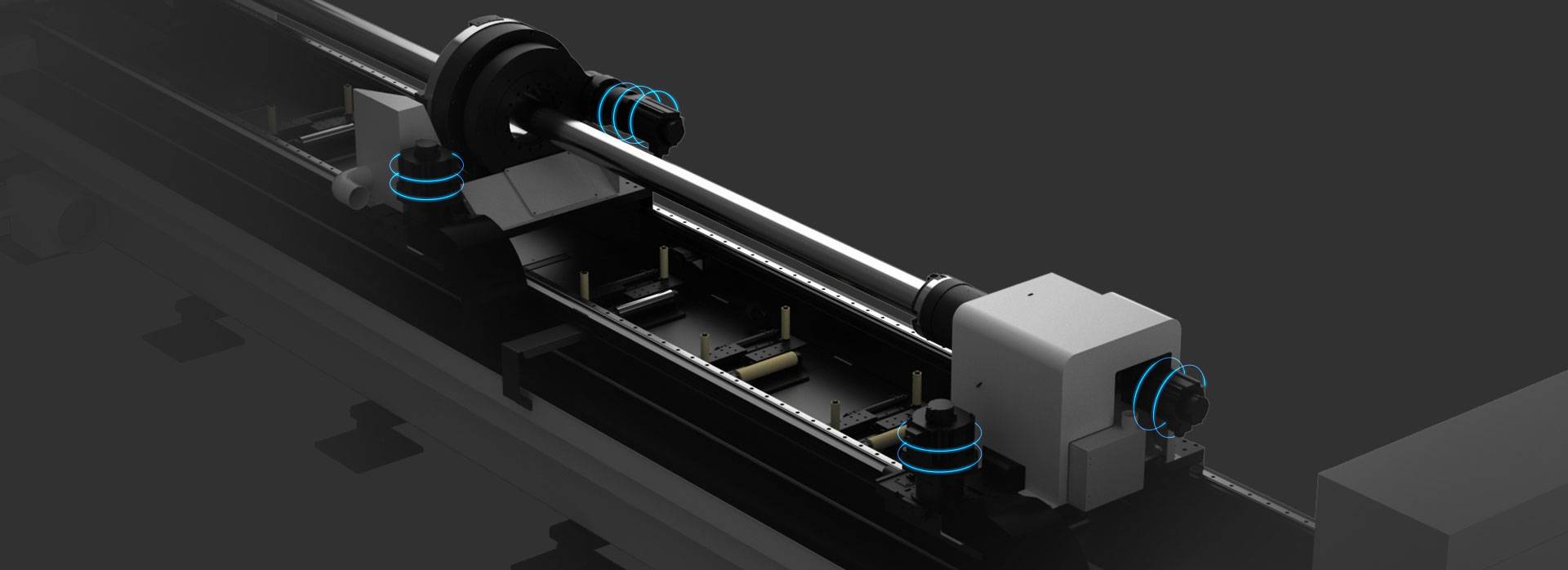
Our CNC Fiber Laser Tube Cutting systems revolutionize metal fabrication by integrating high-precision cutting, punching, and profiling into a single automated workflow. Designed for versatility, this technology handles a wide array of profiles including Round, Square, Rectangular, and Oval tubes, as well as complex L-shaped and U-shaped channels.
- Precision Punching: High-speed hole punching with micron-level accuracy, eliminating the need for mechanical drilling or die-stamping.
- Complex Profiling: Advanced 3D pathing allows for intricate interlocking joints and specialized notch cuts, ideal for structural frames.
- High Material Efficiency: Intelligent nesting software minimizes scrap, reducing raw material costs across large production runs.
- Clean Finish: Delivers oxide-free, burr-free edges that require zero secondary grinding before welding.

Seamlessly processing multiple profiles with consistent precision.
Global Delivery & Logistics



From our high-tech manufacturing facility directly to your global site. PCL WeldCut ensures secure packaging, professional handling, and reliable international logistics to safeguard your equipment throughout the entire journey.