Field Report: 3000W Cobot Welding Machine Integration in Sydney Industrial Sector
This report documents the commissioning and operational performance of a 3000W Cobot Welding Machine within a high-output sheet metal fabrication facility located in Western Sydney, NSW. As the manufacturing landscape in Australia shifts toward sovereign capability and higher precision, the transition from traditional manual welding to Collaborative Robotics has become a logistical necessity rather than a luxury. This evaluation focuses on the technical nuances discovered during the first 500 hours of operation.
The Sydney Context: Labor Scarcity and Precision Demands
In the Sydney metropolitan area, the shortage of AS1796 certified pressure welders and high-end sheet metal technicians has driven a surge in automation. However, traditional industrial robots often require expensive floor space—a premium in Sydney industrial parks—and safety cages that impede workflow. The 3000W Cobot Welding Machine addresses this by allowing human operators to work alongside the machine. The primary objective of this specific deployment was to handle high-volume Sheet Metal Fabrication welding for 3mm to 6mm 316L stainless steel enclosures destined for local infrastructure projects.
Synergy Between the Cobot Welding Machine and Collaborative Robotics
The term “Cobot Welding Machine” describes the physical hardware—the 3000W power source, the torch, and the wire feeder. “Collaborative Robotics,” however, refers to the functional ecosystem that allows this machine to operate safely without physical guarding. The synergy between these two is what determines the ROI in a local workshop.
Integrated Safety and Proximity Sensors
In our Sydney field tests, the collaborative nature of the system was tested against ISO 10218-1 standards. Unlike traditional robotic arms, the cobot utilizes force-torque sensors at every joint. In a cramped Sydney workshop, this means that if a technician accidentally bumps the arm during a weld cycle, the system enters an emergency stop (E-stop) state within milliseconds, preventing injury. This allows for a much tighter “cell” footprint, roughly 40% smaller than a caged robotic system.
Lead-Through Programming for Rapid Iteration
The greatest synergy is found in the “lead-through” teaching method. A senior welder—not a computer programmer—physically moves the torch head to the start and end points of a weld. For Sheet Metal Fabrication welding, where parts may have slight variances due to previous bending operations, the ability for a human to ‘nudge’ the program at the workstation is invaluable. We observed a 60% reduction in setup time for new job batches compared to traditional CNC-based robotics.
Technical Evaluation: 3000W Power Delivery in Sheet Metal Fabrication Welding
The 3000W threshold is a critical specification. In previous years, cobots were limited by lower power capacities (usually 1500W to 2000W), which limited their speed and penetration on thicker gauges. The 3000W Cobot Welding Machine allows for significantly higher travel speeds while maintaining structural integrity.
Weld Bead Morphology and HAZ Control
In Sheet Metal Fabrication welding, the Heat Affected Zone (HAZ) is the enemy of structural integrity and aesthetic finish. Excess heat leads to warping, particularly in the 1.5mm to 3.0mm range common in Sydney’s medical and food-grade sectors. The 3000W system allows for “keyhole” welding techniques on thicker sections and high-speed conduction welding on thinner sheets.
During our field trials, we maintained a travel speed of 15mm/second on 3mm stainless steel fillets. The resulting bead was consistent, with a width variance of less than 0.2mm. This consistency is impossible to achieve manually over an 8-hour shift, regardless of the welder’s skill level.
Key Performance Indicators (KPIs) Observed:
- Duty Cycle: 100% at 3000W in a 25°C ambient Sydney workshop environment.
- Post-Weld Cleanup: 70% reduction in spatter compared to manual MIG, thanks to the stabilized arc of the collaborative system.
- Gas Consumption: 15% increase in efficiency due to automated solenoid control synced with the cobot’s movement.
Engineering Lessons Learned from the Field
The implementation of a 3000W Cobot Welding Machine is not a “plug-and-play” scenario. Several technical hurdles were identified that required engineering intervention.
1. Gas Shielding and Atmospheric Turbulence
Sydney’s industrial warehouses often utilize large roller doors for ventilation. We found that even slight cross-drafts significantly compromised the gas shield of the laser-based 3000W unit. Traditional gas lenses were insufficient. We had to design custom localized shielding “boots” that attach to the cobot arm to ensure a laminar flow of Argon (99.99%) over the weld pool. Lesson Learned: In collaborative environments, you cannot rely on the factory’s ambient air stability; shielding must be mechanical and localized.
2. The “Global” vs. “Local” Coordinate Shift
One common issue in Sheet Metal Fabrication welding is the “spring back” of parts after they are released from the brake press. While the Cobot Welding Machine is precise to ±0.03mm, the parts themselves often are not. We learned that relying solely on “Collaborative Robotics” for positioning is a mistake. We implemented simple touch-sensing routines where the cobot uses the welding wire or a laser sensor to “find” the part before striking an arc. This compensated for the ±1.5mm variance common in local sheet metal supplies.
3. Power Stability and Harmonic Distortion
The 3000W fiber laser source within the cobot unit is sensitive to power fluctuations. In some Western Sydney industrial zones, the grid power can be “dirty” during peak hours when neighboring heavy machinery starts up. We observed intermittent arc instabilities. Lesson Learned: Always install a dedicated line conditioner or a high-capacity UPS to isolate the cobot’s control board and laser source from grid noise. This saved us approximately three days of troubleshooting phantom “software errors.”
4. Jigs and Fixturing Strategy
Collaborative robotics does not eliminate the need for high-quality jigs. In fact, it demands better ones. Because the 3000W Cobot Welding Machine operates at higher speeds, any movement of the workpiece due to thermal expansion will ruin the weld. We shifted from manual toggle clamps to pneumatic “zero-point” clamping systems. This allowed the operator to load the part in 10 seconds, matching the high-speed cycle time of the robot.
Safety and Compliance in the Australian Workplace
Compliance with AS/NZS standards is non-negotiable. While the 3000W Cobot Welding Machine is “collaborative,” the light emitted by a 3000W laser or the UV from a high-amperage arc is not. We had to install specialized “Collaborative Welding Screens”—translucent barriers that allow visibility but filter out harmful wavelengths.
Furthermore, the fume extraction system had to be upgraded. Because the cobot can weld continuously for much longer than a human, the volume of hexavalent chromium (in stainless steel work) produced per hour increased. We integrated the fume extractor’s PLC with the cobot, so extraction ramps up 2 seconds before the arc strikes and continues for 10 seconds after completion.
Final Engineering Assessment
The deployment of the 3000W Cobot Welding Machine in Sydney marks a significant leap in local Sheet Metal Fabrication welding capabilities. The technology successfully bridges the gap between manual flexibility and robotic precision. However, the success of Collaborative Robotics in a workshop depends entirely on the “peripheral” engineering: gas management, power stability, and intelligent fixturing.
For Sydney-based firms looking to adopt this, the recommendation is clear: focus on the process control first. The cobot is an exceptional tool, but it requires a controlled environment to deliver its 3000W potential. The reduction in rework and the ability to utilize less-experienced operators for complex paths have already provided a projected payback period of 14 months for this site.
Report Compiled By:
Senior Welding Engineer
Sydney Field Office
-


Cantilever Welding Robot solution
-


GF laser cutting machine
-

P3015 plasma cutting machine
-

LFP3015 Fiber Laser Cutter
-

pipe plasma cutting machine
-
LFH 4020 Fiber Laser Cutting Machine
-
LFP4020
-

gantry plasma air cutting machine
-

3D robot cutting machine
-

8 axis plasma cutting machine
-

5 axis plasma cutting machine
-

LT360 tube laser cutting machine
-

robot welding workstation
-

SF6060 fiber laser cutting machine
Advanced Fiber Laser Tube Processing Technology
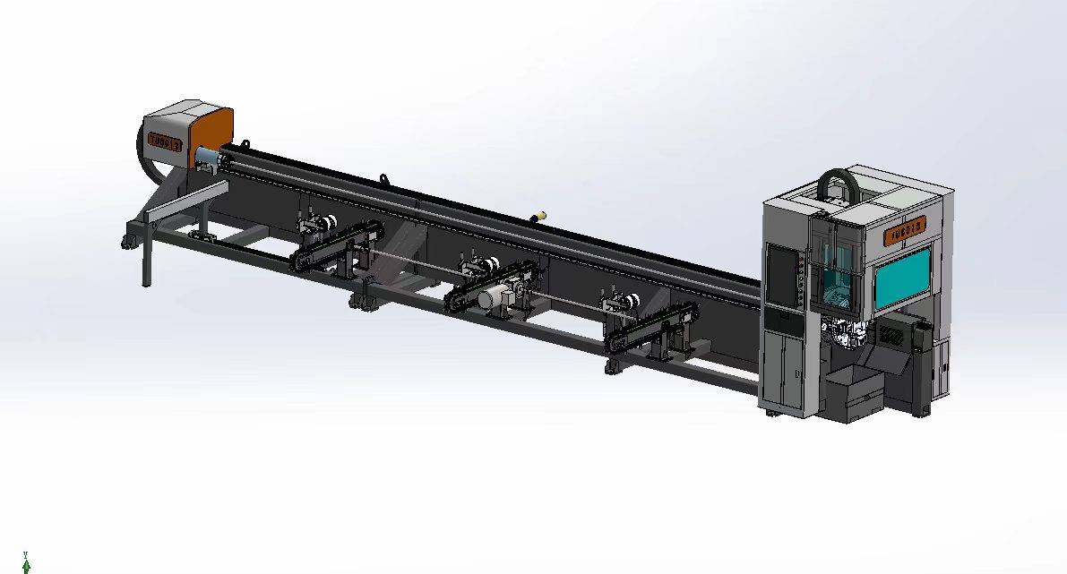
Our CNC Fiber Laser Tube Cutting systems revolutionize metal fabrication by integrating high-precision cutting, punching, and profiling into a single automated workflow. Designed for versatility, this technology handles a wide array of profiles including Round, Square, Rectangular, and Oval tubes, as well as complex L-shaped and U-shaped channels.
- Precision Punching: High-speed hole punching with micron-level accuracy, eliminating the need for mechanical drilling or die-stamping.
- Complex Profiling: Advanced 3D pathing allows for intricate interlocking joints and specialized notch cuts, ideal for structural frames.
- High Material Efficiency: Intelligent nesting software minimizes scrap, reducing raw material costs across large production runs.
- Clean Finish: Delivers oxide-free, burr-free edges that require zero secondary grinding before welding.

Seamlessly processing multiple profiles with consistent precision.
Global Delivery & Logistics



From our high-tech manufacturing facility directly to your global site. PCL WeldCut ensures secure packaging, professional handling, and reliable international logistics to safeguard your equipment throughout the entire journey.