Field Report: Robotic Integration for Heavy Structural Fabrication – Abu Dhabi Industrial Zone
1.0 Project Overview and Site Constraints
This report details the commissioning and performance optimization of a 2000W-class high-output MIG/MAG Welding Robot system at a heavy structural steel facility in Mussafah, Abu Dhabi. The primary objective was to automate the multi-pass welding of 25mm to 40mm S355JR grade thick plate steel welding components used in offshore jacket supports.
Operating in the UAE presents unique environmental challenges. During the July-August window, ambient workshop temperatures frequently exceeded 45°C with relative humidity peaking at 85%. These conditions directly impact the duty cycle of the power source and the cooling efficiency of the torch. Our objective was to implement comprehensive Arc Welding Solutions that could sustain 24/7 production without compromising the mechanical integrity of the weldment or the precision of the robotic arm.
2.0 Synergy: The MIG/MAG Welding Robot and Integrated Arc Solutions
The success of robotic automation in heavy industry depends on the synergy between the mechanical manipulator and the digital power source. In this installation, the MIG/MAG Welding Robot is not merely a path-follower; it serves as the central node for a suite of Arc Welding Solutions. This integration includes real-time seam tracking, adaptive arc pulsing, and automated torch cleaning stations.
2.1 Digital Communication and Arc Stability
We utilized a high-speed Fieldbus interface to link the robot controller with the 2000W-equivalent inverter power source. This allows for millisecond-level adjustments to the arc length and wire feed speed. In the context of the Abu Dhabi heat, maintaining a stable arc is difficult as the electrical resistance in the umbilical cables increases with temperature. By employing a secondary feedback loop—a core part of our Arc Welding Solutions—the system compensates for voltage drops, ensuring the MIG/MAG Welding Robot maintains a constant energy density at the weld pool.
2.2 Gas Dynamics in High-Humidity Environments
A critical lesson learned during the first week of operation was the impact of humidity on hydrogen cracking risks. We moved from a standard 80/20 Argon/CO2 mix to a triple-mix gas (Argon/CO2/O2) to improve wetting on the thick plate steel welding surfaces. The robot’s integrated gas flow sensor was calibrated to detect even minor fluctuations caused by the facility’s heavy-duty cooling fans, which are essential for worker safety but detrimental to shielding gas stability.
3.0 Technical Execution: Thick Plate Steel Welding Protocols
Welding 30mm+ plate requires a strategic approach to heat input and bead sequencing. The MIG/MAG Welding Robot was programmed to execute a multi-pass strategy consisting of a root pass, four fill passes, and two cap passes.
3.1 Groove Preparation and Root Pass Integrity
For thick plate steel welding, we utilized a 60° V-groove preparation. The robot’s laser-based seam tracker was vital here. Due to the weight of the plates, slight fit-up variations (1-2mm) are inevitable. Our Arc Welding Solutions included an “Adaptive Fill” software module that adjusted the robot’s weave width and travel speed in real-time based on the gap volume detected 20mm ahead of the arc.
3.2 Managing Interpass Temperatures
In Abu Dhabi’s climate, the base metal starts at an ambient temperature of 40°C+. With the high current required for 1.2mm solid wire in spray transfer mode (approx. 320A), the interpass temperature can quickly exceed the 250°C limit prescribed in the Welding Procedure Specification (WPS). We programmed “Cooling Off” cycles into the robot’s logic. While one assembly was cooling, the MIG/MAG Welding Robot transitioned to a second workstation. This dual-station setup maximized the 2000W power source utility without overheating the base material, preventing grain growth in the Heat Affected Zone (HAZ).
4.0 Lessons Learned: Field Engineering Observations
Theory often fails when the thermometer hits 50°C. Below are the direct technical takeaways from the Abu Dhabi site integration.
4.1 Thermal Drift of the Robotic Manipulator
We observed a slight thermal expansion in the robot’s aluminum castings during the afternoon shift. This resulted in a 0.5mm deviation in TCP (Tool Center Point) accuracy.
Lesson: We implemented a “TCP Auto-Check” every 10 cycles. The robot touches a reference gauge; if a drift is detected, the software automatically offsets the coordinate system. For thick plate steel welding, a 0.5mm error can lead to lack of sidewall fusion in deep grooves.
4.2 Wire Feed Friction and Conduit Maintenance
The high humidity in the UAE causes the copper coating on some MIG wires to oxidize faster, increasing friction in the liners. This led to “bird-nesting” at the wire feeder of our MIG/MAG Welding Robot.
Lesson: We transitioned to a specialized non-coated wire and upgraded to ceramic-lined conduits. Additionally, we installed a pressurized “Dust-Free” wire pay-off pack to isolate the consumable from the workshop atmosphere. This is a foundational component of reliable Arc Welding Solutions in desert environments.
4.3 Chiller Unit Capacity
The standard internal chiller for the 2000W power source was insufficient for the 100% duty cycle required for heavy thick plate steel welding in Abu Dhabi.
Lesson: We bypassed the internal cooling and integrated an external 5kW industrial chiller. This allowed the torch to remain cool enough for the contact tip to last a full 8-hour shift, reducing downtime significantly.
5.0 Performance Data and ROI Analysis
After three months of operation, the data indicates a significant leap in productivity compared to manual Flux-Cored Arc Welding (FCAW) previously used on-site.
- Deposition Rate: The MIG/MAG Welding Robot maintained a consistent 6.5 kg/hr, compared to the manual average of 3.2 kg/hr (accounting for welder fatigue in heat).
- Defect Rate: Ultrasonic Testing (UT) revealed a rejection rate of less than 0.8%, primarily localized to start/stop points. This is a 90% reduction from manual thick plate steel welding.
- Consumable Efficiency: By optimizing the Arc Welding Solutions parameters, we reduced shielding gas wastage by 22% through the use of synchronized gas pre-flow and post-flow timers.
6.0 Conclusion: The Future of Automation in the UAE
The deployment of the MIG/MAG Welding Robot in Abu Dhabi proves that high-precision automation is viable in extreme climates, provided the environmental variables are engineered into the solution. The integration of robust Arc Welding Solutions—specifically adaptive software and enhanced cooling—is what allows for the successful execution of thick plate steel welding at scale.
For future installations in the Gulf region, the focus must remain on “Over-Spec” cooling and rigorous consumable protection. The robot is capable, but the environment is the limiting factor. Our next phase will involve integrating AI-driven predictive maintenance to monitor the power source’s thermal health, ensuring that the 2000W output remains consistent as the facility scales up production for the upcoming offshore expansion projects.
Report Prepared By:
Senior Welding Engineer
Field Operations Division – Abu Dhabi
-


LT240S tube laser cutting machine
-
LT120S tube laser cutting machine
-
Sale

Tank Fillet Welding Machine
Original price was: $1,000.00.$900.00Current price is: $900.00. -
Sale

MAK100 tube laser cutting machine
Original price was: $5,500.00.$5,000.00Current price is: $5,000.00. -

portable plasma air cutting machine
$1,200.00 -

2in1 fiber laser cutting machine
-

Air cooling Laser welding machine
-

HF h beam laser cutting machine
-

LT240 laser cutting machine
-

Laser welding machine
-


Cobot Welding Station
-

Gantry welding robot solution
-

Tracked Wheeled AGV Welding robot
-

LFH6020 Fiber laser cutting machine
-
LFP6020
-

robotic welidng machine
Advanced Fiber Laser Tube Processing Technology
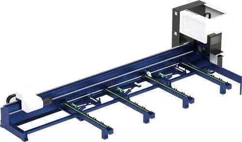
Our CNC Fiber Laser Tube Cutting systems revolutionize metal fabrication by integrating high-precision cutting, punching, and profiling into a single automated workflow. Designed for versatility, this technology handles a wide array of profiles including Round, Square, Rectangular, and Oval tubes, as well as complex L-shaped and U-shaped channels.
- Precision Punching: High-speed hole punching with micron-level accuracy, eliminating the need for mechanical drilling or die-stamping.
- Complex Profiling: Advanced 3D pathing allows for intricate interlocking joints and specialized notch cuts, ideal for structural frames.
- High Material Efficiency: Intelligent nesting software minimizes scrap, reducing raw material costs across large production runs.
- Clean Finish: Delivers oxide-free, burr-free edges that require zero secondary grinding before welding.

Seamlessly processing multiple profiles with consistent precision.
Global Delivery & Logistics



From our high-tech manufacturing facility directly to your global site. PCL WeldCut ensures secure packaging, professional handling, and reliable international logistics to safeguard your equipment throughout the entire journey.