Technical Field Report: Implementation of 2000W Laser Welding Cobot in Manchester
1.0 Introduction and Site Context
This report details the field deployment and calibration of a 2000W Laser Welding Cobot at a precision fabrication facility in Manchester, UK. The objective was to transition high-value Titanium welding operations from manual Gas Tungsten Arc Welding (GTAW) to an automated system leveraging Laser Technology. Manchester’s industrial environment, characterized by its historical reliance on heavy manual fabrication, provides a unique backdrop for this shift toward high-energy density welding. The deployment focused on optimizing throughput for aerospace-grade components while maintaining the stringent metallurgical requirements inherent to reactive metals.
2.0 The Core Technology: 2000W Fiber Laser Source
The heart of this installation is a 2000W continuous wave (CW) fiber laser. When we discuss Laser Technology in a modern Manchester workshop, we are specifically looking at beam quality (M2 < 1.1) and the ability to maintain power stability over long duty cycles. At 2000W, the power density is sufficient to achieve keyhole welding in stainless steel up to 5mm, but for our specific focus on Titanium welding, we operated primarily in a stabilized conduction-limited or transition mode to ensure aesthetic and structural integrity.
The fiber delivery system is critical. In Manchester’s humid climate, the chiller units were calibrated to prevent condensation on the protective windows of the laser head. We observed that even a microscopic layer of moisture on the optics could lead to beam divergence, causing “thermal lensing” that shifts the focal point during a 60-second weld cycle. This is where the Laser Technology must be supported by environmental controls.
3.0 Synergy: The Laser Welding Cobot Interface
The “Cobot” element—a 6-axis collaborative robot—acts as the precision motion controller for the laser head. Unlike traditional industrial robots, the Laser Welding Cobot allows the Manchester-based operators to perform “lead-through” programming. This is vital in a job-shop environment where batch sizes are small (5–50 units).
3.1 Path Repeatability and “Wobble” Dynamics
One of the primary lessons learned during the Manchester deployment was the necessity of the “wobble” function. Laser Technology provides a very narrow spot size (typically 0.15mm to 0.3mm). In real-world fabrication, fit-up tolerances are rarely perfect. By utilizing the Laser Welding Cobot’s integrated wobbling head, we introduced a circular oscillation of 1.5mm at 200Hz. This effectively widened the weld pool, allowing us to bridge gaps that would otherwise result in undercut or lack of fusion. The synergy here is clear: the cobot provides the steady path, while the laser’s high-frequency oscillation compensates for human error in the upstream fit-up process.
4.0 Specialized Application: Titanium Welding Parameters
Titanium welding is notoriously unforgiving. Titanium (specifically Grade 5 Ti-6Al-4V used in this site) has a high affinity for oxygen, nitrogen, and hydrogen at temperatures above 400°C. In the Manchester facility, we had to re-engineer the shielding gas delivery system to match the speed of the Laser Welding Cobot.
4.1 Gas Shielding Challenges
Manual TIG welding allows a welder to move slowly and keep the gas lens over the weld pool. The Laser Welding Cobot moves at speeds exceeding 15mm/s. At these speeds, a standard gas nozzle is insufficient. We implemented a custom-designed “trailing shield” attached to the laser head. This ensured that the cooling weld bead remained under a high-purity Argon (99.999%) blanket until the temperature dropped below the critical oxidation threshold.
We monitored the weld color closely. A silver/straw color was achieved consistently once we synchronized the cobot’s travel speed with the gas flow rate (25 L/min). If the Laser Welding Cobot moved too fast for the trailing shield length, we saw blue/purple oxidation, which is an immediate reject in aerospace specs. The precision of the Laser Technology allows for a much smaller Heat Affected Zone (HAZ) compared to TIG, which significantly reduces the risk of alpha-case formation in the titanium substrate.
5.0 Field Observations: The Manchester Workshop Environment
Implementing a 2000W Laser Welding Cobot in a Manchester-based engineering firm revealed several localized challenges. The electrical grid stability in older industrial estates can lead to voltage sags. We installed a dedicated power conditioner to ensure the Laser Technology source received a consistent 400V 3-phase supply. Without this, the laser’s output power would fluctuate by ±5%, which is enough to cause incomplete penetration in a 3mm Titanium welding joint.
5.1 Operator Upskilling
The transition from “manual welder” to “cobot technician” was surprisingly smooth. The Manchester workforce has a deep tribal knowledge of weld pool physics. By teaching them to adjust the Laser Welding Cobot parameters—specifically the peak power vs. duty cycle—they were able to translate their manual skills into the digital domain. They understood that while the Laser Technology does the melting, the cobot’s pathing dictates the stress distribution in the part.
6.0 Technical Lessons Learned
6.1 Focal Point Drift
During the first week, we noticed inconsistent penetration. Using a laser power meter and beam profiler, we identified that the protective lens was accumulating “spatter” from the titanium. Unlike steel, titanium spatter is highly reflective and aggressive. We increased the “cross-jet” air pressure (using nitrogen) to create a more robust air curtain, protecting the optics. This is a critical maintenance point for any Laser Welding Cobot deployment: the optics are the soul of the machine.
6.2 Fixturing Rigidity
The speed of Laser Technology introduces thermal cycles that are much faster than traditional methods. We found that standard “toggle clamps” weren’t sufficient. The rapid heating and cooling caused the titanium sheets to “pop” or warp slightly mid-weld. We moved to heavy-duty modular d-hole tables and copper backing bars. The copper acts as a heat sink, which, when combined with the Laser Welding Cobot’s precision, resulted in near-zero distortion across a 1200mm weldment.
6.3 Safety Protocols (Class 4 Environment)
Integrating a Laser Welding Cobot requires more than just a curtain. In Manchester, we had to ensure the entire cell was interlocked. Because the cobot can move the laser head in 3D space, the risk of a “stray beam” (specular reflection) off the titanium surface is high. We installed laser-rated (OD7+) viewing windows and ensured the cobot’s software had “deadman” zones where the laser would automatically kill-switch if the head tilted more than 15 degrees from the vertical axis.
7.0 Conclusion: The Future of Fab in the North West
The integration of the 2000W Laser Welding Cobot in Manchester has proven that Laser Technology is no longer reserved for high-volume automotive lines. For Titanium welding, the benefits are clear: a 70% reduction in weld time, a 50% reduction in post-weld grinding/finishing, and superior metallurgical properties. The synergy between the cobot’s ease of use and the laser’s power density allows Manchester’s manufacturing sector to compete on a global scale for high-complexity aerospace and medical contracts.
The key takeaway from this field report is that the machine is only as good as its environment. High-purity gas, stable power, and rigorous optical maintenance are the three pillars that support the Laser Welding Cobot. As we move forward, the focus will be on further refining the “wobble” parameters to handle even more complex geometries in non-ferrous alloys.
End of Report
Prepared by: Senior Welding Engineer, Manchester Field Office.
-


Cantilever Welding Robot solution
-


GF laser cutting machine
-

P3015 plasma cutting machine
-

LFP3015 Fiber Laser Cutter
-

pipe plasma cutting machine
-
LFH 4020 Fiber Laser Cutting Machine
-
LFP4020
-

gantry plasma air cutting machine
-

3D robot cutting machine
-

8 axis plasma cutting machine
-

5 axis plasma cutting machine
-

LT360 tube laser cutting machine
-

robot welding workstation
-

SF6060 fiber laser cutting machine
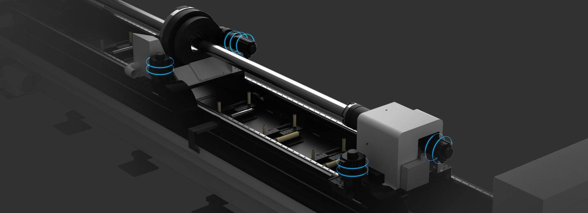
Advanced Fiber Laser Tube Processing Technology
Our CNC Fiber Laser Tube Cutting systems revolutionize metal fabrication by integrating high-precision cutting, punching, and profiling into a single automated workflow. Designed for versatility, this technology handles a wide array of profiles including Round, Square, Rectangular, and Oval tubes, as well as complex L-shaped and U-shaped channels.
- Precision Punching: High-speed hole punching with micron-level accuracy, eliminating the need for mechanical drilling or die-stamping.
- Complex Profiling: Advanced 3D pathing allows for intricate interlocking joints and specialized notch cuts, ideal for structural frames.
- High Material Efficiency: Intelligent nesting software minimizes scrap, reducing raw material costs across large production runs.
- Clean Finish: Delivers oxide-free, burr-free edges that require zero secondary grinding before welding.

Seamlessly processing multiple profiles with consistent precision.
Global Delivery & Logistics



From our high-tech manufacturing facility directly to your global site. PCL WeldCut ensures secure packaging, professional handling, and reliable international logistics to safeguard your equipment throughout the entire journey.