Field Report: Optimization of 2000W Automated MAG Welding Cell – Curitiba Sector
1. Introduction and Site Context
The following report details the technical commissioning and performance optimization of the 2000W Automated MAG Welding Cell installed at the Curitiba, Brazil manufacturing facility. This site, characterized by its high-output requirements and proximity to fluctuating humidity levels in the Paraná region, necessitated a robust integration of advanced Arc Welding Solutions to meet the stringent tolerances required for Copper Components welding.
The primary objective was to transition from manual TIG processes to a fully Automated MAG Welding Cell to increase throughput by 40%. However, welding copper-based alloys via Metal Active Gas (MAG) processes introduces significant metallurgical challenges, primarily due to the high thermal conductivity and rapid solidification rates inherent to the substrate. The synergy between the hardware—the 2000W cell—and the software-driven Arc Welding Solutions was the focal point of this field intervention.
2. Technical Specification of the Automated MAG Welding Cell
The heart of the operation is a 2000W-rated inverter-based power source integrated into a six-axis robotic arm. Unlike standard steel-focused cells, this Automated MAG Welding Cell was custom-configured for high-conductivity applications. In Curitiba, we encountered initial stabilization issues due to voltage drops in the local grid, which were mitigated by installing dedicated line conditioners to ensure the 2000W output remained consistent during peak industrial hours.
2.1. Drive System and Wire Delivery
Copper Components welding requires a non-standard approach to wire delivery. We implemented a four-roll planetary drive system within the cell to prevent “bird-nesting” of the softer copper-alloy wires. Because the 2000W power source operates at high frequencies, any micro-slippage in the wire feeder resulted in instantaneous arc instability. The lesson here was clear: an Automated MAG Welding Cell is only as reliable as its mechanical feeding sub-system.
2.2. Cooling Requirements
Given the high thermal transfer of the workpieces in Curitiba, the cell’s integrated water-cooling unit was upgraded. We observed that the standard radiator could not dissipate heat fast enough when the cell ran at a 100% duty cycle on heavy-gauge Copper Components. We recalibrated the coolant flow rate to 2.5 liters per minute, ensuring the contact tip temperature remained below the threshold for copper-to-copper micro-welding at the orifice.
3. Synergy: Arc Welding Solutions and Process Integration
The success of this deployment relied on treating the hardware not as a standalone unit, but as part of a holistic suite of Arc Welding Solutions. In the Curitiba workshop, “Arc Welding Solutions” refers to the confluence of wave-form manipulation, gas-shielding chemistry, and real-time data monitoring.
3.1. Waveform Manipulation for Copper
Copper’s high thermal conductivity means the heat-affected zone (HAZ) expands rapidly, often leading to burn-through or lack of fusion at the start of the bead. By utilizing specialized Arc Welding Solutions—specifically “Pulse-on-Pulse” technology—we were able to program the Automated MAG Welding Cell to deliver a high-energy “hot start” followed by a stabilized pulsed-spray transfer. This ensured deep penetration into the Copper Components without compromising the integrity of the surrounding thin-walled geometry.
3.2. Gas Dynamics in the Curitiba Environment
Curitiba’s ambient humidity can fluctuate between 50% and 90%. In a MAG process, the “Active” gas component is critical. We moved away from pure Argon to a Tri-Mix (Argon/Helium/CO2) specifically tuned for Copper Components welding. The Helium addition (30%) provided the necessary ionization potential to increase the heat input, while a minute fraction of CO2 (0.5%) stabilized the arc cathode spot, preventing the “wandering arc” syndrome common in high-conductivity automated cells.
4. Deep Dive: Copper Components Welding Challenges
Welding copper is notoriously difficult in an automated environment because the material acts as a massive heat sink. During the first week of the Curitiba trial, we experienced a 15% reject rate due to porosity and lack of side-wall fusion.
4.1. Overcoming Porosity
The porosity was traced to two factors: surface oxides and atmospheric moisture. The Arc Welding Solutions package was updated to include a pre-flow gas purge of 2.0 seconds and a specialized “crater fill” routine. Furthermore, we implemented a mandatory mechanical wire-brushing protocol for all Copper Components immediately prior to loading them into the Automated MAG Welding Cell fixtures.
4.2. Thermal Management and Distortions
Copper expands significantly when heated. To maintain the ±0.5mm tolerance required for the Curitiba project, the cell’s fixtures had to be redesigned. We moved from rigid clamping to “floating” pneumatic clamps that allowed for controlled thermal expansion along the longitudinal axis. This adjustment, combined with the precision of the Automated MAG Welding Cell, reduced post-weld straightening labor by 90%.
5. Field Observations and Lessons Learned
The Curitiba deployment provided several critical insights for future high-power MAG applications in South American industrial hubs.
5.1. The Importance of Tip-to-Work Distance (CTWD)
In an Automated MAG Welding Cell, consistency is everything. We found that for Copper Components welding, even a 1mm deviation in CTWD caused a 15-amp fluctuation in the 2000W power source’s output. We integrated a laser-based seam tracker to adjust the robot’s Z-axis in real-time, ensuring that the Arc Welding Solutions could maintain a constant current density regardless of minor jigging variances.
5.2. Shielding Gas Consistency
A major “lesson learned” involved the gas supply lines. Initial porosity issues were exacerbated by the use of standard rubber hoses which allowed for moisture permeation. We replaced the entire delivery system with stainless steel braided PTFE lines. In the humid climate of Curitiba, this is not an option; it is a requirement for high-quality Copper Components welding.
5.3. Software vs. Reality
The digital twin software used to program the Automated MAG Welding Cell predicted a travel speed of 80cm/min. In practice, the high thermal conductivity of the copper required us to drop to 65cm/min to ensure consistent bead wetting. This 18% discrepancy highlights the need for field engineers to override “idealized” Arc Welding Solutions based on real-world metallurgical behavior.
6. Conclusion and Future Scalability
The integration of the 2000W Automated MAG Welding Cell in Curitiba stands as a benchmark for complex non-ferrous automation. By leveraging specific Arc Welding Solutions—namely customized pulse waveforms and optimized gas mixtures—the facility has successfully transitioned to an automated workflow for Copper Components welding.
Moving forward, the site is looking to implement AI-driven predictive maintenance on the contact tips, as the abrasive nature of copper-alloy wires leads to faster orifice wear than steel. The synergy established between the robotic cell and the metallurgical requirements of the substrate ensures that the Curitiba plant remains at the forefront of Brazilian industrial engineering.
Report End.
Lead Welding Engineer, Site Audit – Curitiba.
-


Cantilever Welding Robot solution
-


GF laser cutting machine
-

P3015 plasma cutting machine
-

LFP3015 Fiber Laser Cutter
-

pipe plasma cutting machine
-
LFH 4020 Fiber Laser Cutting Machine
-
LFP4020
-

gantry plasma air cutting machine
-

3D robot cutting machine
-

8 axis plasma cutting machine
-

5 axis plasma cutting machine
-

LT360 tube laser cutting machine
-

robot welding workstation
-

SF6060 fiber laser cutting machine
Advanced Fiber Laser Tube Processing Technology
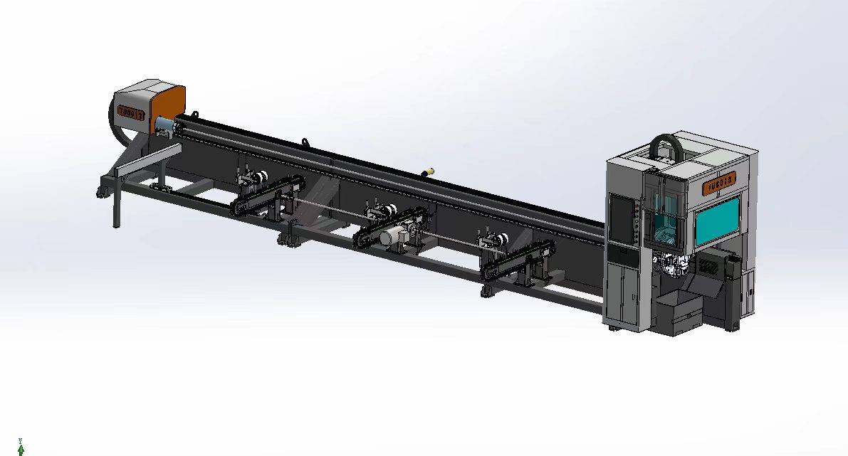
Our CNC Fiber Laser Tube Cutting systems revolutionize metal fabrication by integrating high-precision cutting, punching, and profiling into a single automated workflow. Designed for versatility, this technology handles a wide array of profiles including Round, Square, Rectangular, and Oval tubes, as well as complex L-shaped and U-shaped channels.
- Precision Punching: High-speed hole punching with micron-level accuracy, eliminating the need for mechanical drilling or die-stamping.
- Complex Profiling: Advanced 3D pathing allows for intricate interlocking joints and specialized notch cuts, ideal for structural frames.
- High Material Efficiency: Intelligent nesting software minimizes scrap, reducing raw material costs across large production runs.
- Clean Finish: Delivers oxide-free, burr-free edges that require zero secondary grinding before welding.

Seamlessly processing multiple profiles with consistent precision.
Global Delivery & Logistics



From our high-tech manufacturing facility directly to your global site. PCL WeldCut ensures secure packaging, professional handling, and reliable international logistics to safeguard your equipment throughout the entire journey.