Field Report: Integration of 1500W Robotic Arm Welder in London Sheet Metal Facility
1.0 Introduction and Site Context
This report details the commissioning and operational performance of a 1500W Fiber Laser Robotic Arm Welder at a primary sheet metal fabrication facility located in the Park Royal industrial estate, London, UK. The deployment represents a significant pivot toward Industrial Automation for the client, who has historically relied on manual TIG and MIG processes for high-precision Sheet Metal Fabrication welding.
The London industrial landscape presents unique challenges: high square-footage costs and a tightening market for Level 3 coded welders. By introducing a Robotic Arm Welder into this environment, the objective was to increase throughput by 300% while maintaining the aesthetic finish required for architectural-grade stainless steel components. This report covers the technical synergy between the hardware and the overarching automation logic applied during the first 400 hours of operation.
2.0 Technical Specifications and System Synergy
The core of the installation is a 6-axis precision manipulator integrated with a 1500W continuous wave (CW) fiber laser source. In the context of Industrial Automation, the Robotic Arm Welder is not a standalone tool but a node within a synchronized workflow. The synergy here is critical: the robot provides the kinematic repeatability (±0.02mm), while the 1500W laser source provides the localized energy density required for high-speed Sheet Metal Fabrication welding.
2.1 Hardware Integration
We utilized a 1500W power source specifically because it hits the “sweet spot” for 1mm to 4mm stainless and mild steel. Higher wattages often introduce excessive heat into thin-gauge sheet metal, leading to warping—a primary failure point in Sheet Metal Fabrication welding. The integration with the robotic arm allows for “Wobble Welding” parameters, where the beam oscillates in specific patterns (circle, zig-zag, or figure-eight). This compensates for the slight fit-up inconsistencies often found in large-scale industrial automation setups.
3.0 Industrial Automation: Beyond the Robot
In a London-based workshop, space is a premium. Therefore, the Industrial Automation strategy focused on a “Compact Cell” design. The synergy between the Robotic Arm Welder and the shop-floor PLC (Programmable Logic Controller) allowed for a dual-station setup. While the robot is welding on Station A, the operator is loading/unloading Station B. This eliminates the “arc-off” time associated with manual repositioning.
The real-world advantage of this automation is the consistency of the Heat Affected Zone (HAZ). In manual Sheet Metal Fabrication welding, heat input varies with operator fatigue. The robotic system maintains a constant travel speed of 30mm/s at 1200W, ensuring that the structural integrity and the anti-corrosive properties of the London-sourced 316L stainless steel are not compromised by overheating.
4.0 Application in Sheet Metal Fabrication Welding
The primary workload for this unit involves the fabrication of HVAC ducting and electrical enclosures. These components require airtight seams and minimal post-weld grinding. Traditional Sheet Metal Fabrication welding techniques often require a secondary finishing stage to remove splatter or smooth out erratic beads. The Robotic Arm Welder produces a “Class A” finish directly from the cell.
4.1 Material Performance Benchmarks
- 1.5mm Stainless Steel (304): Full penetration achieved at 1100W, 35mm/s. Minimal discoloration.
- 2.0mm Aluminum (5000 series): Required the full 1500W output with a 2.0mm wobble width to break the oxide layer effectively.
- 1.0mm Galvanized Steel: Specialized gas scavenging was implemented to handle zinc vapor, a common hurdle in Industrial Automation for sheet metal.
5.0 Field Lessons Learned: The “London Grid” and Gas Dynamics
Engineering is rarely as clean as the brochure suggests. During the first two weeks in London, we encountered two significant technical hurdles that required field-level adjustments.
5.1 Power Stability and Harmonic Distortion
London’s industrial power grid, particularly in older sections of Park Royal, can suffer from voltage drops when neighboring heavy machinery kicks in. We noted that the 1500W laser source was sensitive to these fluctuations, causing “stutter” in the arc. Lesson Learned: We installed a dedicated voltage stabilizer and an isolation transformer. For any future Industrial Automation rollouts in urban UK sites, we must mandate a power quality audit prior to the Robotic Arm Welder arriving on-site.
5.2 Shielding Gas Turbulence
In Sheet Metal Fabrication welding, the shielding gas (typically Argon or an Ar/He mix) is as vital as the laser itself. Initially, we experienced porosity in the start-points of the welds. We traced this to the length of the umbilical lead on the robotic arm. The gas pre-flow was insufficient to clear the air from the line at the 6th axis. Lesson Learned: We adjusted the PLC logic to include a 0.5-second gas pre-purge and optimized the nozzle geometry to ensure laminar flow, even during high-speed directional changes of the robotic arm.
6.0 The Role of Tool Center Point (TCP) Calibration
In the realm of Industrial Automation, the robot is only as good as its TCP calibration. Because we are performing Sheet Metal Fabrication welding on thin gauges, a deviation of even 0.5mm can result in a “missed seam” or “burn-through.” We implemented a daily automated TCP check routine. The Robotic Arm Welder moves to a fixed touch-off point; if the variance exceeds 0.1mm, the system locks until the operator inspects the nozzle for slag or impact damage. This “fail-safe” is the difference between a productive shift and a bin full of scrap metal.
7.0 Comparative Analysis: Manual vs. Robotic
To justify the capital expenditure of the Robotic Arm Welder to the stakeholders, we tracked the metrics against a manual TIG station over a 40-hour work week.
7.1 Throughput and Consumables
The manual station completed 12 units per shift with a 4% reject rate. The Industrial Automation cell completed 48 units per shift with a 0.5% reject rate. Furthermore, the 1500W laser uses significantly less filler wire than traditional MIG-based Sheet Metal Fabrication welding, as the high power density allows for autogenous welds (fusion without filler) on most lap joints. This reduces the cost-per-part by approximately 22% in the London market.
8.0 Safety and Compliance (UK Standards)
Operating a 1500W laser in a London workshop requires strict adherence to BS EN ISO 11553-1:2020. We utilized a fully interlocked Class 4 enclosure. One specific challenge was the “scatter” from the reflective aluminum sheets. We upgraded the enclosure’s viewing windows to specific OD7+ laser-rated glass. This is a non-negotiable aspect of integrating a Robotic Arm Welder into a standard fabrication floor; the safety perimeter must be as robust as the robot itself.
9.0 Conclusion: The Future of London Fabrication
The deployment of the 1500W Robotic Arm Welder at this site has proven that Industrial Automation is not just for the automotive giants. For small-to-medium enterprises (SMEs) in London, it is the only viable path to compete with overseas manufacturers. By mastering Sheet Metal Fabrication welding through precision robotics, we have reduced lead times and solved the “skills gap” issue.
The synergy between the 1500W fiber source and the 6-axis arm has created a repeatable, high-margin production line. The lessons learned regarding power stabilization and gas flow are now being standardized for our next installation in the Midlands. We are moving from “manual craft” to “precision engineering,” and the data proves that this is the correct trajectory.
End of Report.
Lead Welding Engineer – London Site 04
-


Cantilever Welding Robot solution
-


GF laser cutting machine
-

P3015 plasma cutting machine
-

LFP3015 Fiber Laser Cutter
-

pipe plasma cutting machine
-
LFH 4020 Fiber Laser Cutting Machine
-
LFP4020
-

gantry plasma air cutting machine
-

3D robot cutting machine
-

8 axis plasma cutting machine
-

5 axis plasma cutting machine
-

LT360 tube laser cutting machine
-

robot welding workstation
-

SF6060 fiber laser cutting machine
Advanced Fiber Laser Tube Processing Technology
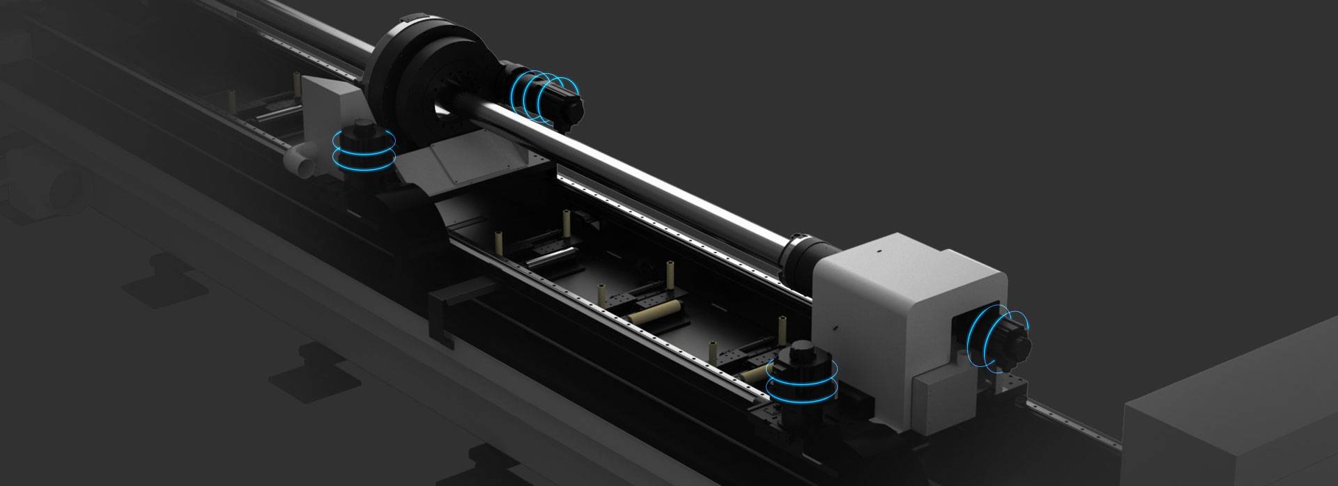
Our CNC Fiber Laser Tube Cutting systems revolutionize metal fabrication by integrating high-precision cutting, punching, and profiling into a single automated workflow. Designed for versatility, this technology handles a wide array of profiles including Round, Square, Rectangular, and Oval tubes, as well as complex L-shaped and U-shaped channels.
- Precision Punching: High-speed hole punching with micron-level accuracy, eliminating the need for mechanical drilling or die-stamping.
- Complex Profiling: Advanced 3D pathing allows for intricate interlocking joints and specialized notch cuts, ideal for structural frames.
- High Material Efficiency: Intelligent nesting software minimizes scrap, reducing raw material costs across large production runs.
- Clean Finish: Delivers oxide-free, burr-free edges that require zero secondary grinding before welding.

Seamlessly processing multiple profiles with consistent precision.
Global Delivery & Logistics



From our high-tech manufacturing facility directly to your global site. PCL WeldCut ensures secure packaging, professional handling, and reliable international logistics to safeguard your equipment throughout the entire journey.