Field Engineering Report: Implementation of 1500W Laser Welding Cobot in Structural Steel Applications
1.0 Introduction and Site Overview
This report summarizes the technical field evaluation of a 1500W Laser Welding Cobot system deployed at a mid-sized fabrication facility in Columbus, Ohio. The objective was to transition a portion of the facility’s structural steel welding workload from traditional Gas Metal Arc Welding (GMAW) to automated Laser Technology. The focus remains on improving throughput for sub-assemblies, specifically bracketry and hollow structural sections (HSS) used in light commercial frames.
Ohio’s manufacturing environment presents specific challenges, including fluctuating ambient humidity in the workshop and a highly competitive labor market. The adoption of a Laser Welding Cobot aims to mitigate these factors by providing a stabilized, high-speed welding solution that requires less specialized manual dexterity than TIG or high-end MIG, while maintaining superior metallurgical properties.
2.0 The Synergy of Laser Technology and Collaborative Robotics
The core of this implementation is the marriage of a 1500W continuous wave (CW) fiber laser source with a six-axis collaborative robot arm. In the “Ohio workshop” context, laser technology provides the raw energy density required for deep penetration with minimal heat input. However, the manual application of handheld laser welding often suffers from beam instability due to operator fatigue.
By integrating the Laser Welding Cobot, we have decoupled the precision of the beam path from the operator’s steady hand. The cobot maintains a constant focal point and travel speed—parameters that are critical when dealing with the high power density of a 1500W source. This synergy allows for “set and forget” repeatability on complex geometries that would typically require a highly skilled welder to navigate.
2.1 Technical Specifications of the 1500W Source
The 1500W fiber laser utilized in this field test operates at a 1080nm wavelength. We focused on utilizing “wobble” parameters (oscillating the beam in a circular or zig-zag pattern) to compensate for the tighter fit-up tolerances required by laser technology compared to traditional arc welding. In structural steel welding, where mill scale and slight gaps are common, the cobot’s ability to execute a precise 2.0mm wobble at a frequency of 250Hz was instrumental in achieving consistent root fusion.
3.0 Application in Structural Steel Welding
The primary material under evaluation was A36 carbon steel, ranging from 3mm to 6mm in thickness. While 1500W is considered “entry-level” for heavy industrial laser applications, its performance in light structural steel welding proved significant.
3.1 Penetration and Heat Affected Zone (HAZ)
One of the primary “lessons learned” during the Ohio field trials was the drastic reduction in the Heat Affected Zone. In traditional GMAW, the energy is dispersed over a wide area, leading to thermal distortion in thin-gauge structural members. Using laser technology, the energy is concentrated. Our cross-sectional macro-etch tests showed a HAZ reduction of approximately 65% compared to pulsed-MIG. This is critical for maintaining the structural integrity of the base metal and reducing post-weld straightening labor.
3.2 Joint Configuration and Fit-up
We encountered a significant learning curve regarding joint preparation. Structural steel welding in many Ohio shops often relies on “fill-and-kill” techniques where large gaps are bridged with heavy wire feed. The Laser Welding Cobot is less forgiving. We found that gaps exceeding 0.5mm resulted in undercut or “blow-through” at 1500W. To address this, we implemented a dedicated jigging station to ensure tight fit-up, demonstrating that the success of laser technology is 50% optics and 50% fixturing.
4.0 Practical Lessons from the Ohio Field Deployment
4.1 Environmental Factors: The “Ohio Humidity” Variable
A technical detail often overlooked is the chilling system for the laser source. During the humid Ohio summer, we observed condensation on the protective windows of the laser head.
Lesson Learned: We had to recalibrate the chiller’s dew point tracking to prevent moisture accumulation. Failure to do so results in the 1500W beam being absorbed by water droplets, which can shatter the protective lens. High-purity Nitrogen was also used as a shield gas to ensure the structural steel welding remained free of porosity, which is more prevalent in high-humidity environments.
4.2 Safety Interlocks and Enclosures
Because the Laser Welding Cobot is a Class 4 laser system, the “collaborative” aspect is limited by optical safety. Unlike a standard cobot that can work side-by-side with humans, the laser requires a light-tight enclosure. We designed a modular “Laser Safety Zone” using OD7+ rated curtains. The lesson here is that the “footprint” of a Laser Welding Cobot is larger than the robot itself due to the safety standoff distances required to protect other shop personnel from reflected 1500W radiation.
4.3 Wire Feed Integration
While many believe laser welding is autogenous (no filler), structural steel welding almost always requires filler wire for reinforcement. We integrated a dedicated cold-wire feeder. The synchronization between the cobot’s travel speed and the wire feed rate is the most volatile variable. If the wire isn’t fed precisely into the leading edge of the melt pool, the 1500W beam will simply vaporize the wire before it reaches the joint.
5.0 Performance Metrics: Laser vs. Traditional Methods
During the two-week evaluation period, we tracked several key performance indicators (KPIs) for the Laser Welding Cobot compared to manual GMAW for a standard 12-piece structural bracket assembly.
- Travel Speed: The 1500W laser achieved speeds of 1.2 meters per minute, roughly 3x faster than manual GMAW.
- Consumables: Shield gas consumption (Nitrogen) was higher per minute but lower per part due to the increased speed.
- Post-Weld Processing: Grinding and spatter removal were reduced by 90%. In structural steel welding, this represents a massive cost saving that often outweighs the initial investment in laser technology.
6.0 Metallurgical Observations
The cooling rate of a laser weld is significantly faster than that of an arc weld. When welding A36 structural steel, there was initial concern regarding the formation of martensite in the fusion zone, which could lead to brittleness. However, the 1500W power level combined with a 1.5mm/s wire feed provided enough heat retention to allow for a normalized grain structure. Hardness testing across the weld profile showed values within acceptable limits for ASTM A36 standards, confirming that the Laser Welding Cobot is viable for load-bearing components if pulsed correctly.
7.0 Conclusion and Recommendations
The deployment of the 1500W Laser Welding Cobot in Ohio has proven that laser technology is no longer restricted to high-precision aerospace or medical applications. It is a workhorse tool for structural steel welding provided the shop environment adapts to its requirements.
Key Recommendations for Future Implementation:
- Upstream Accuracy: Invest in laser-cutting or precision-sawing for all raw structural stock to meet the 0.5mm gap tolerance.
- Operator Training: Shift the focus of training from “welding technique” to “program optimization.” The skill required is now in the management of the Laser Welding Cobot interface rather than the physical manipulation of the torch.
- Dynamic Fixturing: Use heavy-duty, toggle-clamp fixtures to counteract the slight thermal expansion that occurs during the high-speed pass, ensuring the beam remains centered on the joint.
Final Assessment: The 1500W system is the “sweet spot” for Ohio’s light-to-medium structural fabricators, offering a blend of manageable power requirements and high-velocity production capability.
Report Prepared By:
Senior Welding Engineer
Field Operations – Ohio District
-


LT240S tube laser cutting machine
-
LT120S tube laser cutting machine
-
Sale

Tank Fillet Welding Machine
Original price was: $1,000.00.$900.00Current price is: $900.00. -
Sale

MAK100 tube laser cutting machine
Original price was: $5,500.00.$5,000.00Current price is: $5,000.00. -

portable plasma air cutting machine
$1,200.00 -

2in1 fiber laser cutting machine
-

Air cooling Laser welding machine
-

HF h beam laser cutting machine
-

LT240 laser cutting machine
-

Laser welding machine
-


Cobot Welding Station
-

Gantry welding robot solution
-

Tracked Wheeled AGV Welding robot
-

LFH6020 Fiber laser cutting machine
-
LFP6020
-

robotic welidng machine
Advanced Fiber Laser Tube Processing Technology
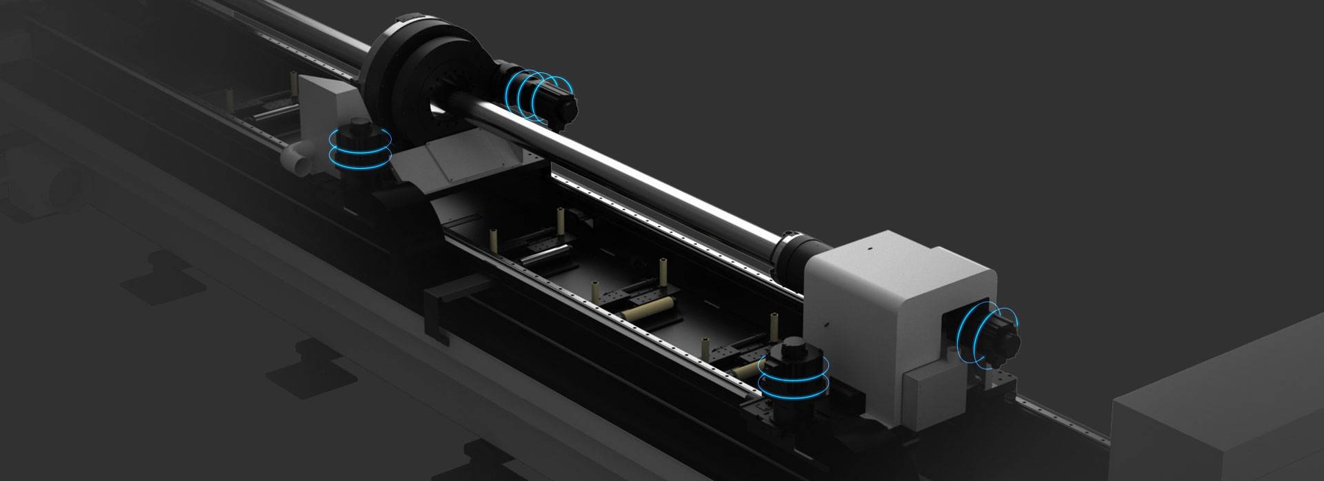
Our CNC Fiber Laser Tube Cutting systems revolutionize metal fabrication by integrating high-precision cutting, punching, and profiling into a single automated workflow. Designed for versatility, this technology handles a wide array of profiles including Round, Square, Rectangular, and Oval tubes, as well as complex L-shaped and U-shaped channels.
- Precision Punching: High-speed hole punching with micron-level accuracy, eliminating the need for mechanical drilling or die-stamping.
- Complex Profiling: Advanced 3D pathing allows for intricate interlocking joints and specialized notch cuts, ideal for structural frames.
- High Material Efficiency: Intelligent nesting software minimizes scrap, reducing raw material costs across large production runs.
- Clean Finish: Delivers oxide-free, burr-free edges that require zero secondary grinding before welding.

Seamlessly processing multiple profiles with consistent precision.
Global Delivery & Logistics



From our high-tech manufacturing facility directly to your global site. PCL WeldCut ensures secure packaging, professional handling, and reliable international logistics to safeguard your equipment throughout the entire journey.