Field Technical Report: Deployment of 1000W Cobot Welding Machine in Seoul High-Precision Aerospace District
This report summarizes the field implementation, parameter optimization, and operational outcomes of the 1000W fiber laser Cobot Welding Machine deployed at a specialized fabrication facility in Seongsu-dong, Seoul. The primary objective was to transition from manual GTAW (Gas Tungsten Arc Welding) to automated Collaborative Robotics for thin-gauge Grade 2 and Grade 5 Titanium welding applications.
1. Site Context and Infrastructure Challenges
The Seoul facility is characteristic of urban high-tech manufacturing hubs: limited floor space, high power costs, and a demand for extreme precision in small-batch runs. Traditional industrial robots were discarded due to the footprint required for safety fencing and the rigidity of their programming environments.
The introduction of Collaborative Robotics allowed us to integrate the welding cell directly into the existing workflow without physical barriers. However, the urban power grid stability in the district required the installation of a dedicated 10kW voltage stabilizer to ensure the 1000W laser source maintained a consistent power density. Titanium is unforgiving; a 2% fluctuation in power translates directly into penetration depth inconsistencies and potential atmospheric contamination due to disrupted puddle dynamics.
2. Technical Specifications of the Cobot Welding Machine
The unit deployed is a 1000W continuous wave (CW) fiber laser integrated with a 6-axis collaborative arm. Unlike traditional CO2 or YAG systems, this Cobot Welding Machine utilizes a wobble-head delivery system. For the Seoul project, we utilized the following baseline configuration:
- Laser Source: 1000W Ytterbium Fiber.
- Wobble Frequency: Adjustable from 0–300Hz (Optimized at 140Hz for Titanium).
- Wobble Width: 1.5mm to 2.5mm for fillet joints.
- Interface: Direct teaching mode via hand-guiding (Lead-through programming).
3. The Synergy of Collaborative Robotics and Precision Placement
The true value of Collaborative Robotics in this application is not merely the replacement of human hands, but the stabilization of the “Torch-to-Work” distance. In Titanium welding, the focal point of the laser must remain within a ±0.5mm tolerance to prevent the formation of brittle intermetallic compounds or excessive oxidation in the heat-affected zone (HAZ).
During the Seoul field trials, we observed that the Cobot Welding Machine could maintain a travel speed of 12mm/s on 2.0mm Ti-6Al-4V plates with a repeatability that manual operators could not match over an 8-hour shift. The collaborative nature allowed the senior welder to “hand-guide” the robot to the start point, record the path, and then step back to monitor the gas shielding—a hybrid workflow that maximizes human expertise while leveraging robotic consistency.
4. Titanium Welding: Atmospheric Control and Heat Management
Titanium welding requires an oxygen-free environment (less than 50 ppm). In the Seoul workshop, we faced challenges with ambient humidity. The Cobot Welding Machine was outfitted with a custom-engineered trailing shield and a back-purge fixture.
4.1. Gas Shielding Parameters
We utilized 99.999% pure Argon. One critical lesson learned was the synchronization between the Collaborative Robotics movement and the gas pre-flow/post-flow.
- Pre-flow: 2.0 seconds.
- Post-flow: 5.0 seconds (Essential to prevent “blueing” or “straw” discoloration as the weld cools).
- Trailing Shield: Mounted directly to the cobot flange, ensuring the shield remained concentric to the weld path even during complex 3D maneuvers.
4.2. Thermal Input and Distortion
Titanium has low thermal conductivity. Excessive heat leads to grain growth, which degrades the fatigue strength of the joint. The 1000W Cobot Welding Machine allowed us to use a high-energy-density beam with a narrow spot size, significantly reducing the total heat input compared to GTAW. By utilizing the Collaborative Robotics software to pulse the laser at 2000Hz (simulated pulsing through duty cycle modulation), we achieved full penetration on 3mm butt joints with a HAZ 60% narrower than manual benchmarks.
5. Real-World Lessons from the Seoul Workshop
5.1. The “Human-in-the-Loop” Fallacy
One early mistake was assuming the Collaborative Robotics system could be operated by a non-welder. While the machine handles the motion, the Titanium welding process requires a deep understanding of metallurgy. In Seoul, we found that the best results occurred when the senior welding engineer programmed the “wobble” parameters while the cobot handled the physical strain of the long-seam welds. Collaborative does not mean “unskilled”; it means “augmented.”
5.2. Jigs and Fixturing Rigidity
Because the Cobot Welding Machine exerts zero physical force on the workpiece (unlike resistance welding), we initially used light-duty magnets and clamps. We quickly learned that the thermal expansion of Titanium during the laser pass is enough to shift the part by 0.8mm—enough to miss the focal point. We had to upgrade to heavy-duty copper-chill bars to both sink the heat and lock the geometry.
5.3. Surface Preparation
In the Seoul field site, we encountered issues with weld porosity. Investigation revealed that the high-tech degreasers used by the local staff left a microscopic residue that the laser vaporized into the puddle. We switched to a mechanical stainless-steel wire brush followed by an ACS-grade acetone wipe immediately prior to the Collaborative Robotics cycle. This reduced the reject rate from 12% to less than 0.5%.
6. Productivity and ROI Analysis
In a high-rent district like Seoul, every square meter must produce. The Cobot Welding Machine setup occupied only 4 square meters.
- Manual GTAW Output: 4 units/hour (including fit-up and cleaning).
- Cobot Output: 14 units/hour.
The 350% increase in throughput was driven by the elimination of “arc-off” time. The Collaborative Robotics arm moves between joints at 500mm/s, whereas a manual operator must reposition, regrip, and refocus after every 100mm of bead.
7. Safety and Compliance in the South Korean Context
South Korean KOSHA (Korea Occupational Safety and Health Agency) standards for Collaborative Robotics are stringent. We utilized the cobot’s force-sensing capabilities to stop motion upon a 50N impact. Furthermore, since we were using a 1000W laser, we installed a local “shadow-box” enclosure—a modular, light-tight curtain that surrounds the immediate work zone—allowing the operator to remain in the vicinity without Class 4 laser eyewear, provided they stay outside the designated “Laser Controlled Area.”
8. Conclusion and Future Outlook
The deployment of the 1000W Cobot Welding Machine in Seoul confirms that for Titanium welding, the precision of Collaborative Robotics is no longer a luxury but a necessity for meeting aerospace-grade specifications. The reduction in “Blueing” (oxidation) and the consistency of the root bead profile justify the initial capital expenditure.
Moving forward, we recommend integrating an AI-based vision system for real-time seam tracking. While the current teaching method is effective, the slight variations in part fit-up from Seoul’s upstream suppliers occasionally require manual override. Automating this adjustment via the cobot’s controller would further de-risk the process and solidify the facility’s position as a leader in precision titanium fabrication.
Report Prepared By: Senior Welding Engineer, Field Operations Div.
Location: Seoul, South Korea
Date: October 2023
-


Cantilever Welding Robot solution
-


GF laser cutting machine
-

P3015 plasma cutting machine
-

LFP3015 Fiber Laser Cutter
-

pipe plasma cutting machine
-
LFH 4020 Fiber Laser Cutting Machine
-
LFP4020
-

gantry plasma air cutting machine
-

3D robot cutting machine
-

8 axis plasma cutting machine
-

5 axis plasma cutting machine
-

LT360 tube laser cutting machine
-

robot welding workstation
-

SF6060 fiber laser cutting machine
Advanced Fiber Laser Tube Processing Technology
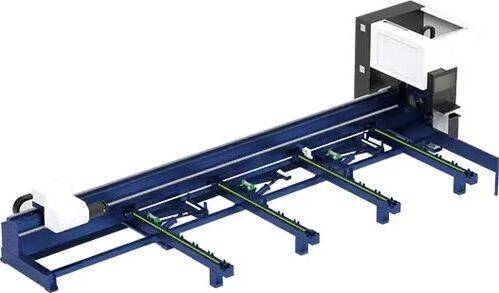
Our CNC Fiber Laser Tube Cutting systems revolutionize metal fabrication by integrating high-precision cutting, punching, and profiling into a single automated workflow. Designed for versatility, this technology handles a wide array of profiles including Round, Square, Rectangular, and Oval tubes, as well as complex L-shaped and U-shaped channels.
- Precision Punching: High-speed hole punching with micron-level accuracy, eliminating the need for mechanical drilling or die-stamping.
- Complex Profiling: Advanced 3D pathing allows for intricate interlocking joints and specialized notch cuts, ideal for structural frames.
- High Material Efficiency: Intelligent nesting software minimizes scrap, reducing raw material costs across large production runs.
- Clean Finish: Delivers oxide-free, burr-free edges that require zero secondary grinding before welding.

Seamlessly processing multiple profiles with consistent precision.
Global Delivery & Logistics



From our high-tech manufacturing facility directly to your global site. PCL WeldCut ensures secure packaging, professional handling, and reliable international logistics to safeguard your equipment throughout the entire journey.