Field Engineering Report: Integration of 1000W Cobot Welding Machine in Sheet Metal Fabrication
1.0 Project Overview and Site Conditions
This report details the commissioning and field performance of a 1000W fiber laser Cobot Welding Machine at a mid-tier sheet metal fabrication welding facility in Rocklea, Brisbane. The objective was to transition high-frequency, low-volume (HMLV) stainless steel housing projects from manual TIG stations to an automated workflow using Collaborative Robotics.
Brisbane’s specific environmental factors—primarily high ambient humidity and seasonal temperature fluctuations—were identified as primary variables affecting the fiber laser’s chiller performance and gas shielding stability. The deployment focused on 1.5mm to 3.0mm Grade 316 stainless steel and 5052 aluminum alloys, typical of the local marine and food processing sectors.
2.0 Technical Specification and Power Delivery
The 1000W power rating was selected over the 1500W alternatives to minimize the Heat Affected Zone (HAZ) on thin-gauge enclosures. In sheet metal fabrication welding, excess power often leads to burn-through or excessive “oil-canning” (warpage). At 1000W, we achieved a stable keyhole weld on 2mm stainless at a travel speed of 25mm/s, which is approximately four times faster than our best manual operators.
2.1 Laser Modulation and Pulse Control
The synergy between the Cobot Welding Machine’s power source and the arm’s velocity is critical. We utilized a continuous wave (CW) source but implemented frequency modulation at the software level to manage heat input during corner transitions. Without the precision of collaborative robotics, maintaining a consistent 0.2mm standoff distance on curved geometries is functionally impossible for a manual welder over an eight-hour shift.
3.0 The Role of Collaborative Robotics in the Workshop
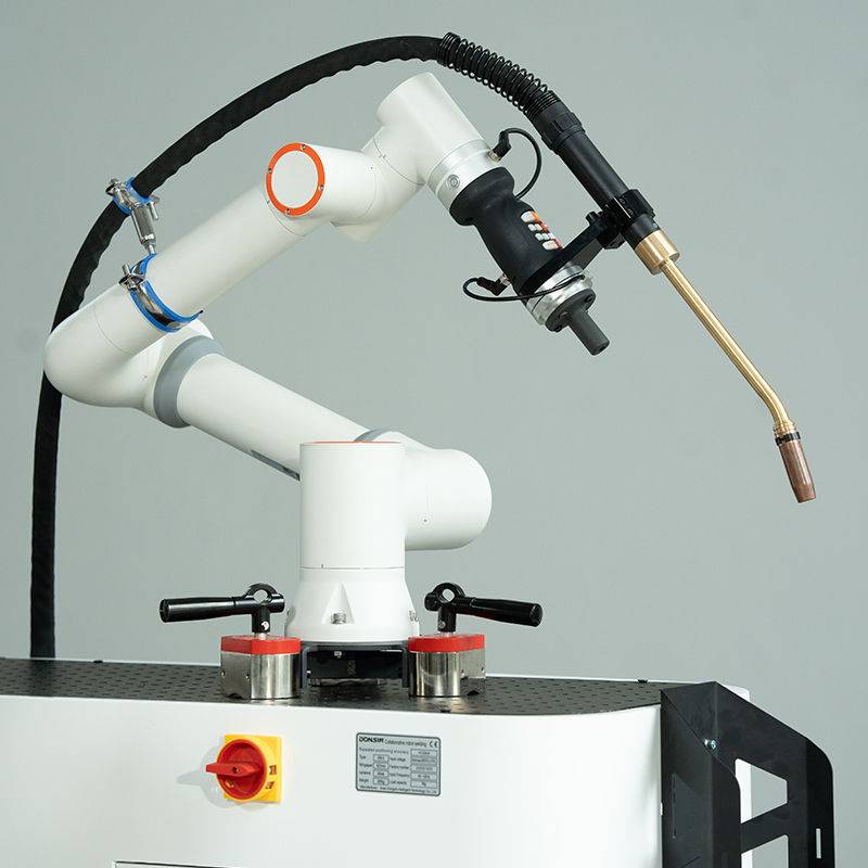
The shift from traditional industrial robots to collaborative robotics represents a fundamental change in Brisbane shop-floor dynamics. Traditional cells require light curtains, physical fencing, and a massive footprint. In the cramped quarters of a standard Rocklea industrial unit, the Cobot Welding Machine allows for a “fence-less” operation (subject to local AS/NZS 4024.1 safety audits).
3.1 Safety and Interaction
The “Collaborative” aspect was tested through the integration of torque sensors in each joint. If the arm encounters an unexpected obstacle—such as a misplaced jig or an operator’s arm—the system executes a Category 0 stop. However, the real engineering value is “Lead-Through Programming.” Instead of writing lines of G-code, our senior welders move the arm physically to the start and end points. This keeps the “welding intelligence” with the welder, not a software programmer who has never struck an arc.
4.0 Practical Application: Sheet Metal Fabrication Welding
Sheet metal is notoriously unforgiving. The primary challenge at this site was “fit-up tolerance.” Unlike heavy plate welding, 1.5mm sheet metal tends to have gaps that vary by 0.5mm due to upstream shearing or bending inaccuracies.
4.1 Wobble Parameters and Gap Bridging
To compensate for these tolerances, we utilized the “wobble” function integrated into the Cobot Welding Machine. By oscillating the laser beam in a circular or “figure-8” pattern (width: 1.5mm, frequency: 150Hz), the collaborative robotics system could bridge gaps that would typically cause a standard laser to “miss” the seam. This reduced our scrap rate from 8% in manual TIG to less than 1% in the automated cell.
4.2 Shielding Gas Dynamics
In the Brisbane heat, gas turbulence can be an issue if shop fans are directed poorly. We switched from a standard 100% Argon setup to an Argon/Helium mix for the aluminum runs to increase thermal conductivity. The cobot’s ability to maintain a constant torch angle (precisely 15 degrees lead) ensured that the gas envelope remained laminar, preventing the porosity issues we previously observed in manual samples.
5.0 Field Performance Data and ROI
Over a 30-day observation period, the following metrics were recorded:
- Throughput: A 320% increase in completed units per shift compared to the manual TIG baseline.
- Consumables: A 40% reduction in wire consumption due to the precision of the integrated wire feeder.
- Energy: The 1000W fiber source proved significantly more efficient than the old 300A TIG inverters, though the chiller unit’s 24/7 cycling in the Brisbane sun offset some of these gains.
6.0 Lessons Learned: The “Real World” Engineering Perspective
Deploying a Cobot Welding Machine is not a “plug-and-play” endeavor. Several technical hurdles required field-side engineering pivots.
6.1 Jigging and Fixturing
The most significant lesson: Your automation is only as good as your jigging. Collaborative robotics removes the human’s ability to “tweak” the torch on the fly to account for a piece of metal that is lifting off the table. We had to redesign our toggle-clamp tables to include heat-sink backing bars. In sheet metal fabrication welding, if the part moves 1mm, the weld fails. Precision fixturing is the hidden cost of cobot adoption.
6.2 The Humidity Factor
The Rocklea facility experienced optics fogging during the early morning shifts (85% relative humidity). We had to implement a nitrogen-purge system for the laser head and ensure the chiller was set to 2-3 degrees above the dew point, rather than a fixed 20°C. This is a critical adjustment for any Cobot Welding Machine operating in subtropical Australian climates.
6.3 Wire Feed Consistency
Standard MIG wire feeders often struggle with the rapid, jerky movements of a cobot arm during air-moves. We switched to a “push-pull” synchronized system. For 0.8mm stainless wire, the tension must be exact; too much and the wire deforms, too little and the cobot’s rapid re-positioning causes bird-nesting at the drive rolls.
7.0 Synergy: Why the 1000W Cobot Wins in Brisbane
The synergy between the Cobot Welding Machine and collaborative robotics lies in the democratization of automation. In the Brisbane market, skilled TIG welders are increasingly difficult to find and retain. By using the cobot to handle the “drudge work”—the long, linear seams and repetitive circular bungs—we freed up our senior engineers to focus on complex manifold assemblies and quality control.
Furthermore, sheet metal fabrication welding requires a level of consistency that human physiology cannot maintain over an 8-hour shift in 35-degree heat. The cobot doesn’t suffer from heat fatigue or “Monday morning” inconsistency. The 1000W output is the “sweet spot” for this application, providing enough punch for 3mm base plates while remaining delicate enough for 1.2mm skins.
8.0 Conclusion
The deployment at the Brisbane site confirms that collaborative robotics is the viable path forward for Australian SMEs. The 1000W Cobot Welding Machine successfully addressed the bottleneck in sheet metal fabrication welding, provided that the engineering team accounts for environmental humidity and invests heavily in precision jigging. Future iterations will look at integrating AI-driven vision systems to further reduce the reliance on rigid fixturing, allowing the cobot to “see” and adjust to part deviations in real-time.
Signed,
Senior Welding Engineer
Project Field Report #BRIS-1000W-04
-


Cantilever Welding Robot solution
-


GF laser cutting machine
-

P3015 plasma cutting machine
-

LFP3015 Fiber Laser Cutter
-

pipe plasma cutting machine
-
LFH 4020 Fiber Laser Cutting Machine
-
LFP4020
-

gantry plasma air cutting machine
-

3D robot cutting machine
-

8 axis plasma cutting machine
-

5 axis plasma cutting machine
-

LT360 tube laser cutting machine
-

robot welding workstation
-

SF6060 fiber laser cutting machine
Advanced Fiber Laser Tube Processing Technology
Our CNC Fiber Laser Tube Cutting systems revolutionize metal fabrication by integrating high-precision cutting, punching, and profiling into a single automated workflow. Designed for versatility, this technology handles a wide array of profiles including Round, Square, Rectangular, and Oval tubes, as well as complex L-shaped and U-shaped channels.
- Precision Punching: High-speed hole punching with micron-level accuracy, eliminating the need for mechanical drilling or die-stamping.
- Complex Profiling: Advanced 3D pathing allows for intricate interlocking joints and specialized notch cuts, ideal for structural frames.
- High Material Efficiency: Intelligent nesting software minimizes scrap, reducing raw material costs across large production runs.
- Clean Finish: Delivers oxide-free, burr-free edges that require zero secondary grinding before welding.

Seamlessly processing multiple profiles with consistent precision.
Global Delivery & Logistics



From our high-tech manufacturing facility directly to your global site. PCL WeldCut ensures secure packaging, professional handling, and reliable international logistics to safeguard your equipment throughout the entire journey.