Field Commissioning Report: 1000W Automated MAG Welding Cell Implementation
Project Overview and Site Specifics: Curitiba, Brazil
The following report details the technical commissioning and operational stabilization of the 1000W Automated MAG Welding Cell at the Curitiba industrial facility. This site primarily focuses on the high-volume fabrication of structural components for the South American agricultural sector. The primary challenge identified during the initial site survey was the integration of high-speed automation with the demanding requirements of galvanized pipe welding. Curitiba’s specific environmental factors—notably the high relative humidity during the summer months—required specific adjustments to the shielding gas delivery systems to prevent moisture contamination in the weld pool.
The deployment objective was to replace a series of manual stations with a centralized automated solution. By leveraging modern Arc Welding Solutions, the goal was to increase throughput by 40% while reducing the reject rate associated with porosity and zinc-inclusion defects common in galvanized applications.
Technical Configuration of the Automated MAG Welding Cell
The heart of this installation is the 1000W power-modulated Automated MAG Welding Cell. Unlike standard constant-voltage machines, this unit utilizes a high-speed inverter capable of pulsing at frequencies that allow for precise droplet transfer control. In the context of MAG (Metal Active Gas) welding, managing the heat input is critical when dealing with the thin-wall piping utilized in this facility.
Hardware Integration and Motion Control
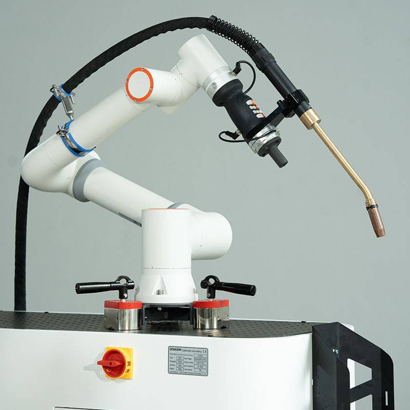
The cell incorporates a six-axis robotic manipulator synchronized with a dual-station head-and-tailstock positioner. This allows for continuous welding around the circumference of the pipe without extinguishing the arc, which is vital for maintaining a consistent thermal profile. The 1000W rating refers to the stabilized control output of the power source during short-circuit transfer modes, optimized for 0.8mm and 1.0mm wire diameters.
Synergy with Arc Welding Solutions
The term “Arc Welding Solutions” refers to the holistic integration of the power source, the wire feeder, and the digital control interface. In Curitiba, we implemented a proprietary pulsed-MAG waveform specifically designed for coated steels. This software-driven solution manages the arc length dynamically. When the sensors detect an increase in resistance—often caused by zinc vapor interference—the system adjusts the current peak in real-time to maintain arc stability. This synergy ensures that the Automated MAG Welding Cell doesn’t just “run” but actively adapts to the metallurgical variables of the workpiece.
The Challenge of Galvanized Pipe Welding
Galvanized pipe welding is notoriously difficult due to the low boiling point of the zinc coating (approximately 906°C) compared to the melting point of the steel substrate (approximately 1538°C). As the arc moves across the joint, the zinc vaporizes instantly. If the weld pool solidifies too quickly, these vapors are trapped, resulting in gross porosity and “wormholes.”
Metallurgical Considerations
In the Curitiba workshop, the galvanized layer thickness averaged 60 microns. Standard MAG welding often results in excessive spatter as the zinc vapor explodes through the molten puddle. To counteract this, the Automated MAG Welding Cell was programmed with a specific “back-and-forth” oscillation pattern. This motion allows the arc to lead the puddle slightly, pre-vaporizing a portion of the zinc before the main weld pool reaches the joint. This technique, integrated into our broader Arc Welding Solutions, significantly reduced post-weld cleanup time.
Shielding Gas Optimization
Given the local climate in Brazil, we opted for an 8% CO2 / 92% Argon mix. The higher Argon content provides the necessary arc ionization for the 1000W cell’s high-speed pulsing, while the 8% CO2 provides just enough surface tension to prevent the weld pool from becoming too fluid—a common issue when welding galvanized pipe in the 2G or 5G positions.
Operational Performance and Data Analysis
After three weeks of continuous operation, the data extracted from the cell’s monitoring software indicated a significant improvement in deposition efficiency. The Automated MAG Welding Cell maintained an “Arc-On” time of 78%, a drastic increase over the 30% typically seen in manual operations.
Porosity Mitigation Results
Radiographic testing (RT) of the first 500 units revealed a porosity rate of less than 1.5%. In the previous manual setup, this figure often hovered around 12%. The consistency of the Automated MAG Welding Cell is the primary driver here; the robot maintains a perfect 12mm contact-to-work distance (CTWD), which is nearly impossible for a manual welder to sustain over an 8-hour shift, especially when battling the fumes generated by galvanized pipe welding.
Thermal Management
The 1000W power source proved sufficient for the 3mm wall thickness of the pipes. We utilized a “Stitch-Pulse” logic where the arc intensity is momentarily dropped at the overlap points of the circular weld. This prevented burn-through, which was a major concern during the initial programming phase in the Curitiba facility.
Lessons Learned from the Field
Transitioning a shop to an Automated MAG Welding Cell involves more than just “plug and play.” Several hard-won lessons were documented during this deployment:
1. Extraction is Non-Negotiable
The volume of zinc oxide fumes produced by a high-speed cell is immense. We had to retrofit the torch with an integrated high-vacuum extraction nozzle. Standard overhead hoods were insufficient. For any future Arc Welding Solutions involving galvanized pipe welding, source extraction must be integrated into the initial cell design to prevent sensor fouling and protect the equipment.
2. Wire Selection and Feedability
We initially attempted to use standard ER70S-6 wire. However, we found that a specialized wire with slightly higher silicon and manganese content worked better to “kill” the weld pool and float out the zinc impurities. Furthermore, the wire feed rollers required a specific U-groove profile to prevent crushing the wire, which can lead to micro-arc instabilities that the 1000W controller interprets as a fault.
3. The “Curitiba Factor”: Humidity Control
We observed a spike in hydrogen-induced cracking during the first week. The culprit was moisture condensation on the galvanized pipes stored in the unheated warehouse. We implemented a pre-heat pass—using the robot’s secondary program—to run a low-amperage dry pass over the joint. This flash-evaporated the moisture before the actual welding pass. This is a crucial procedural adjustment for any Arc Welding Solutions deployed in humid, subtropical climates.
Maintenance and Longevity of the Cell
To maintain the precision of the Automated MAG Welding Cell, a daily maintenance schedule was established. Zinc dust is conductive and abrasive. It settles on the robotic arm joints and inside the power source cabinets. In Curitiba, we mandated a twice-daily blow-out of the feed system and the torch head using dry compressed air.
The contact tips also required more frequent replacement than in standard mild-steel applications. Zinc vapor tends to “plate” onto the copper tip, eventually narrowing the orifice and causing “burn-back.” We switched to a silver-plated contact tip, which, while more expensive, increased the mean time between failures (MTBF) from 4 hours to 24 hours of continuous operation.
Final Conclusion on Site Implementation
The deployment in Curitiba confirms that an Automated MAG Welding Cell, when paired with the correct Arc Welding Solutions, is the most effective way to handle the complexities of galvanized pipe welding at scale. The synergy between the 1000W power source’s digital control and the mechanical precision of the robotic system has transformed the facility’s output. By addressing the metallurgical challenges of zinc vapor through waveform manipulation and environmental control, the project has exceeded its initial KPIs. The key to success was not just the hardware, but the specific field adjustments made to accommodate the local environment and the unique properties of the galvanized substrate.
-


LT240S tube laser cutting machine
-
LT120S tube laser cutting machine
-
Sale

Tank Fillet Welding Machine
Original price was: $1,000.00.$900.00Current price is: $900.00. -
Sale

MAK100 tube laser cutting machine
Original price was: $5,500.00.$5,000.00Current price is: $5,000.00. -

portable plasma air cutting machine
$1,200.00 -

2in1 fiber laser cutting machine
-

Air cooling Laser welding machine
-

HF h beam laser cutting machine
-

LT240 laser cutting machine
-

Laser welding machine
-


Cobot Welding Station
-

Gantry welding robot solution
-

Tracked Wheeled AGV Welding robot
-

LFH6020 Fiber laser cutting machine
-
LFP6020
-

robotic welidng machine
Advanced Fiber Laser Tube Processing Technology
Our CNC Fiber Laser Tube Cutting systems revolutionize metal fabrication by integrating high-precision cutting, punching, and profiling into a single automated workflow. Designed for versatility, this technology handles a wide array of profiles including Round, Square, Rectangular, and Oval tubes, as well as complex L-shaped and U-shaped channels.
- Precision Punching: High-speed hole punching with micron-level accuracy, eliminating the need for mechanical drilling or die-stamping.
- Complex Profiling: Advanced 3D pathing allows for intricate interlocking joints and specialized notch cuts, ideal for structural frames.
- High Material Efficiency: Intelligent nesting software minimizes scrap, reducing raw material costs across large production runs.
- Clean Finish: Delivers oxide-free, burr-free edges that require zero secondary grinding before welding.

Seamlessly processing multiple profiles with consistent precision.
Global Delivery & Logistics


From our high-tech manufacturing facility directly to your global site. PCL WeldCut ensures secure packaging, professional handling, and reliable international logistics to safeguard your equipment throughout the entire journey.