Optimizing Maritime Structural Fabrication with Plasma Beam Processing
In the domain of industrial shipbuilding, the structural integrity of a vessel depends on the geometric precision of its skeletal components. Heavy-duty sections, including H-beams, I-beams, and bulb flats, require sophisticated processing to ensure that intersections and joints align with sub-millimeter accuracy. The transition from manual layout and mechanical sawing to automated structural beam processing centers has redefined throughput metrics. By utilizing Plasma Cutting heads integrated with Laser Seam Tracking, shipyards can achieve a level of consistency that satisfies stringent classification society standards while minimizing material waste.
Enhancing Intersection Accuracy via Laser Seam Tracking
One of the primary challenges in processing large-scale structural beams is the inherent deviation in raw material. H-beams and channels often exhibit “camber,” “sweep,” or “twist” from the mill, which can lead to significant errors during the fit-up stage if the cutting path remains static. A Beam Processing Center utilizes laser seam tracking to perform real-time surface mapping of the workpiece. This sensor-driven approach allows the control system to adjust the plasma torch path dynamically, compensating for any material irregularities.
The precision of the intersection is critical for the structural load distribution of a ship’s hull and deck. When two beams meet, the “cope” or “notch” must be exact to allow for a tight fit-up. Laser tracking ensures that the plasma arc initiates and terminates at the precise spatial coordinates required by the CAD/CAM model, regardless of whether the beam is slightly warped. This high-fidelity sensing eliminates the need for manual “re-work” or corrective grinding, which are common bottlenecks in traditional shipyards.
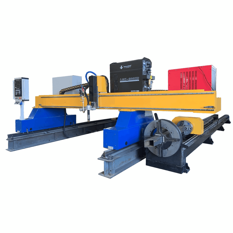
Plasma Cutting Dynamics for High-Output Shipbuilding
Plasma cutting remains the industry standard for Shipbuilding due to its ability to pierce and sever thick carbon steel and high-tensile alloys at rapid speeds. Unlike mechanical methods, plasma allows for complex 3D geometries to be cut into the web and flanges of a beam in a single pass. The thermal energy of the plasma arc is concentrated, resulting in a narrow kerf and a minimal heat-affected zone (HAZ) when compared to oxy-fuel systems. This preservation of material properties is vital for the fatigue resistance of maritime structures.
Low Maintenance Requirements for H-Beam Processing
From an industrial engineering perspective, the Total Cost of Ownership (TCO) is a pivotal metric. Traditional mechanical drilling and sawing lines involve significant downtime for tool changes, sharpening, and coolant management. In contrast, plasma cutting precision systems for H-beams are designed for high availability. The primary consumables—electrodes, nozzles, and shields—are easily replaceable and offer predictable lifespans based on arc-on time.
The non-contact nature of plasma cutting further reduces mechanical wear on the machine structure. Since there is no physical force applied to the beam during the cutting process, the structural frame of the processing center experiences less vibration and stress. This results in longer calibration intervals and a reduction in the maintenance of guide rails and drive motors. For shipyards operating on 24/7 schedules, the reliability of a plasma-based beam center ensures that the assembly line remains fed with ready-to-weld components.
Advanced Beveling and Weld Preparation
Shipbuilding requires complex edge preparation to ensure full-penetration joints in thick-walled sections. A 5-axis or 6-axis robotic arm within the beam processing center allows the plasma torch to perform multi-angle beveling on all sides of the beam. Whether the design specifies a V-bevel, Y-bevel, or K-bevel, the system executes these cuts with high beveling accuracy.
The integration of the laser tracking system is particularly beneficial during the beveling phase. By measuring the actual thickness and orientation of the flange, the system can adjust the torch angle to maintain a consistent root face and bevel angle. This consistency is paramount for automated downstream processes, as it ensures that the joint geometry remains within the tolerance window required for high-quality assembly. Precise beveling also reduces the volume of filler metal required, directly impacting the overall cost of the vessel’s construction.
Data Integration and Workflow Efficiency
Modern beam processing centers act as data-driven hubs within the shipyard. By importing DSTV or IFC files directly from the naval architecture software, the system interprets the exact requirements for every hole, cope, and bevel. The laser tracking system provides a feedback loop, recording the “as-built” dimensions of the processed beam. This data can be used for quality assurance documentation and to optimize the nesting of parts to reduce scrap rates.
Furthermore, the automation of these centers reduces the labor intensity of the fabrication shop. A single operator can oversee the processing of multiple beams, focusing on material handling and system monitoring rather than manual measurement. This shift in labor utilization allows for higher production volumes without a proportional increase in headcount, addressing the skilled labor shortages often seen in the heavy manufacturing sector.
Conclusion: The Strategic Impact on Shipyard Productivity
The implementation of a Beam Processing Center with Laser Seam Tracking represents a strategic investment in technical capability and operational efficiency. By prioritizing plasma cutting for its speed and versatility, shipyards can overcome the challenges of material deformation and complex geometries. The focus on intersection accuracy and precise beveling ensures that the final assembly is structurally sound and cost-effective. As maritime engineering continues to push the boundaries of vessel size and complexity, the role of high-precision automated beam processing will remain a cornerstone of modern shipbuilding infrastructure.
-


Cantilever Welding Robot solution
-


GF laser cutting machine
-

P3015 plasma cutting machine
-

LFP3015 Fiber Laser Cutter
-

pipe plasma cutting machine
-
LFH 4020 Fiber Laser Cutting Machine
-
LFP4020
-

gantry plasma air cutting machine
-

3D robot cutting machine
-

8 axis plasma cutting machine
-

5 axis plasma cutting machine
-

LT360 tube laser cutting machine
-

robot welding workstation
-

SF6060 fiber laser cutting machine
Advanced Fiber Laser Tube Processing Technology
Our CNC Fiber Laser Tube Cutting systems revolutionize metal fabrication by integrating high-precision cutting, punching, and profiling into a single automated workflow. Designed for versatility, this technology handles a wide array of profiles including Round, Square, Rectangular, and Oval tubes, as well as complex L-shaped and U-shaped channels.
- Precision Punching: High-speed hole punching with micron-level accuracy, eliminating the need for mechanical drilling or die-stamping.
- Complex Profiling: Advanced 3D pathing allows for intricate interlocking joints and specialized notch cuts, ideal for structural frames.
- High Material Efficiency: Intelligent nesting software minimizes scrap, reducing raw material costs across large production runs.
- Clean Finish: Delivers oxide-free, burr-free edges that require zero secondary grinding before welding.

Seamlessly processing multiple profiles with consistent precision.
Global Delivery & Logistics



From our high-tech manufacturing facility directly to your global site. PCL WeldCut ensures secure packaging, professional handling, and reliable international logistics to safeguard your equipment throughout the entire journey.