Engineering Review: Water-cooled Robotic Arm Welder – Pune, India
In this article
- Field Engineering Report: Integration of Water-Cooled Robotic Arm Welder in Pune Automotive…
- 1. Executive Summary: The Transition to Automated Tool Steel Management
- 2. Hardware Configuration and Industrial Automation Synergy
- 3. Technical Deep-Dive: Tool Steel Welding Challenges
- 4. Lessons Learned: Field Observations from the Pune Site
- 5. Metallurgical Integrity and Quality Assurance
- 6. The Economic Impact of Automation in Pune
- 7. Final Recommendations for Senior Management
Field Engineering Report: Integration of Water-Cooled Robotic Arm Welder in Pune Automotive Cluster
1. Executive Summary: The Transition to Automated Tool Steel Management
This report details the commissioning and optimization of a high-duty-cycle Robotic Arm Welder system at a Tier-1 automotive tooling facility in Chakan, Pune. The objective was to transition from manual GTAW (Gas Tungsten Arc Welding) to a fully integrated Industrial Automation solution for the surfacing and repair of H13 and D2 Tool Steel welding components.
In the high-ambient-temperature environment of Pune, the primary technical hurdle was maintaining interpass temperature consistency while ensuring the Robotic Arm Welder maintained a 100% duty cycle. By utilizing a water-cooled torch configuration and advanced thermal sensors integrated into the Industrial Automation loop, we achieved a 40% reduction in cycle time and a significant increase in deposit uniformity.
2. Hardware Configuration and Industrial Automation Synergy
The core of the installation is a 6-axis Robotic Arm Welder with a 10kg payload capacity, optimized for a reach that covers two distinct welding stations. However, the “arm” is merely the executioner; the intelligence lies in the Industrial Automation stack. In Pune’s manufacturing landscape, automation is often misunderstood as simple repetition. Here, we treated it as a dynamic process control system.
2.1 The Robotic Arm Welder Specifications
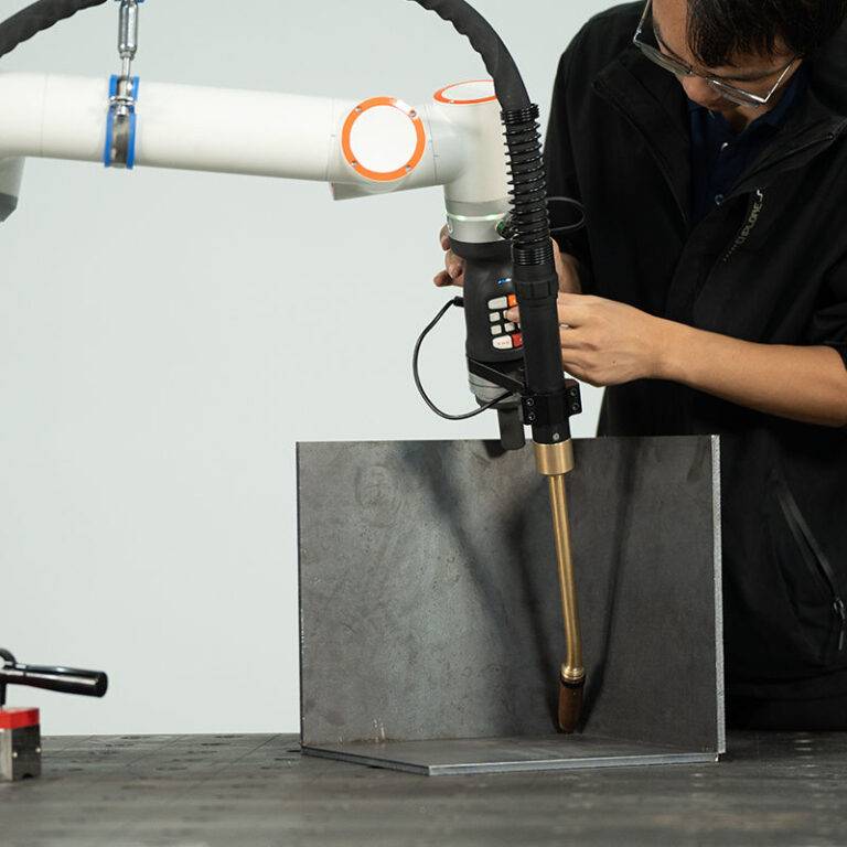
The unit utilizes a hollow-wrist design to prevent cable snagging—a common failure point in high-speed Industrial Automation lines. We opted for a water-cooled MIG/MAG torch instead of air-cooled variants. Given the Tool Steel welding requirements—where preheat temperatures often exceed 300°C—an air-cooled torch would suffer from premature contact tip failure and liner degradation. The water-cooling circuit is monitored via a digital flow meter tied directly to the robot’s E-stop circuit; if the flow drops below 1.5 L/min, the process halts immediately to protect the investment.
2.2 PLC and Sensor Integration
The synergy between the Robotic Arm Welder and the broader Industrial Automation framework is managed via a Profinet interface. We integrated laser-based seam tracking to compensate for the slight thermal expansion of the tool steel dies during the welding process. This is critical: Tool Steel welding involves high heat inputs that can shift the workpiece by 0.5mm to 1.2mm. Without the “eyes” of automation, the robot would be welding air or creating inclusion-heavy beads off-center.
3. Technical Deep-Dive: Tool Steel Welding Challenges
Welding tool steel is notoriously difficult due to its high carbon and alloy content, which increases hardenability and the risk of cold cracking (Hydrogen Induced Cracking). In the Pune workshop, where humidity can fluctuate significantly, managing the hydrogen potential is as important as the weld path itself.
3.1 Thermal Management and Preheating
For H13 Tool Steel welding, we established a strict preheat protocol of 350°C. The Robotic Arm Welder was programmed with specific “thermal dwell” pauses. Using an infrared pyrometer integrated into the Industrial Automation logic, the robot will not strike an arc unless the base metal is within the ±20°C window of the target preheat. This prevents the formation of brittle martensite in the Heat Affected Zone (HAZ).
3.2 Filler Metal and Shielding Gas Dynamics
We utilized a specialized 1.2mm metal-cored wire designed for hot-work tool steels. The Robotic Arm Welder was calibrated for a pulsed-spray transfer mode. This mode is essential for Industrial Automation because it provides a stable arc with minimal spatter, reducing the downtime required for nozzle cleaning. The shielding gas—a 92% Argon / 8% CO2 mix—was delivered through a mass flow controller to ensure consistent coverage regardless of the shop’s ambient drafts.
4. Lessons Learned: Field Observations from the Pune Site
Deploying a Robotic Arm Welder in an Indian industrial hub presents unique environmental challenges that don’t always appear in the manufacturer’s manual. The following are the “boots-on-the-ground” findings from the past six months of operation.
4.1 Power Quality and Grounding
The Industrial Automation components (specifically the encoders in the robotic joints) are highly sensitive to voltage spikes common in the local power grid. We observed “ghost offsets” in the weld path during the afternoon peak load hours. Lesson: Dedicated isolation transformers and a copper-plate grounding system specifically for the Robotic Arm Welder are non-negotiable. Once the grounding was overhauled, the path deviation errors disappeared.
4.2 Water-Cooling Maintenance in Hard Water Regions
Pune’s industrial water supply can have high calcium content. Initially, we used standard filtered water for the torch cooling system. Within three weeks, we saw a 15% decrease in cooling efficiency due to scale buildup in the torch neck. Lesson: Always use a closed-loop deionized water system with a dedicated chiller. For Tool Steel welding, where the torch is hovering over a 350°C workpiece, any drop in cooling efficiency leads to “burn-back” of the wire to the contact tip.
4.3 The “Human-Automation” Interface
One of the biggest hurdles wasn’t the Robotic Arm Welder itself, but the transition of the manual welders to “Robot Operators.” There is a tendency to override the Industrial Automation safety speeds. We implemented multi-level password protection on the teach pendant to ensure that the calibrated parameters for Tool Steel welding (travel speed, wire feed, and voltage) remain locked within the qualified Welding Procedure Specification (WPS) limits.
5. Metallurgical Integrity and Quality Assurance
Post-weld analysis of the tool steel components showed a significant improvement in grain structure compared to manual welding. The Robotic Arm Welder provides a level of “constant velocity” that a human hand cannot replicate. This is vital for Tool Steel welding because variations in travel speed lead to localized overheating, which causes “soft spots” in the die (dropping from 52 HRC to 40 HRC).
5.1 Hardness Testing Results
Upon tempering the H13 dies at 550°C, the hardness profile across the weld, HAZ, and base metal was within a 3-point HRC range. This uniformity is a direct result of the Industrial Automation system’s ability to maintain a precise interpass temperature. By utilizing the water-cooled torch, we were able to run longer beads without the torch nozzle expanding and affecting the Gas Cup-to-Work Distance (GCWD), which is a common cause of porosity in automated setups.
6. The Economic Impact of Automation in Pune
The ROI (Return on Investment) for this Robotic Arm Welder was calculated based on “rework reduction.” In manual Tool Steel welding, the rejection rate due to internal porosity or cracking was approximately 12%. Since the Industrial Automation system took over, the rejection rate has dropped to less than 0.5%.
Furthermore, the ability to run the system through “Shift B” and “Shift C” with minimal supervision has allowed the Pune facility to take on higher-volume contracts from European OEMs that require documented process control—something only an automated system can provide through data logging of every weld bead’s parameters.
7. Final Recommendations for Senior Management
- Expand Chiller Capacity: As we move into the summer months in Pune, increase the chiller capacity for the Robotic Arm Welder to account for ambient temperatures exceeding 42°C.
- Standardize Wire Sourcing: Stick to the certified metal-cored wire for Tool Steel welding; cheap local alternatives have inconsistent diameters that cause slippage in the automated wire drive.
- Predictive Maintenance: Use the Industrial Automation software to track “arc-on time” and proactively change the torch liner every 500kg of wire to prevent feed-related downtime.
In conclusion, the integration of the Robotic Arm Welder has fundamentally changed the shop’s capability. By treating Industrial Automation as a metallurgical tool rather than just a mechanical one, we have solved the inherent difficulties of Tool Steel welding in a high-demand environment.
Report Filed By:
Senior Welding Engineer, Site Operations – Pune