Engineering Review: Precision CMT Robotic Arm Welder – Rotterdam, Netherlands
In this article
- Field Engineering Report: Implementation of Precision CMT Robotic Arm Welder in Rotterdam…
- 1.0 Executive Summary of Field Operations
- 2.0 Integration of Robotic Arm Welder and Industrial Automation
- 2.1 The Kinematic Framework
- 2.2 Communication Protocols and Control Logic
- 3.0 Technical Analysis: Mild Steel Welding Performance
- 3.1 Metallurgy and Heat Input
- 3.2 Shielding Gas Dynamics in Coastal Environments
- 4.0 Industrial Automation: The Workflow Efficiency
- 4.1 Cycle Time and Duty Cycle Optimization
- 4.2 Sensor Integration and Error Handling
- 5.0 Practical Field Observations and Lessons Learned
- 5.1 Wire Feed Consistency
- 5.2 The “Grounding” Factor
Field Engineering Report: Implementation of Precision CMT Robotic Arm Welder in Rotterdam Port Operations
1.0 Executive Summary of Field Operations
This report details the technical deployment and performance evaluation of the Precision CMT (Cold Metal Transfer) Robotic Arm Welder at our Rotterdam facility. The objective was to integrate high-speed Industrial Automation into our existing fabrication line for offshore structural components, specifically focusing on large-scale Mild Steel welding. Over a 14-day observation period, we monitored the synergy between robotic kinematics and the CMT power source to establish new baseline metrics for penetration depth, cycle time, and post-weld rework requirements.
The Rotterdam environment presents unique challenges, primarily high ambient humidity and saline air, which significantly impact the surface oxidation of Mild Steel welding consumables. Our findings indicate that while the Robotic Arm Welder provides superior repeatability, the industrial automation logic must be tuned to account for environmental fluctuations and material variability inherent in European S355 grade steels.
2.0 Integration of Robotic Arm Welder and Industrial Automation
2.1 The Kinematic Framework
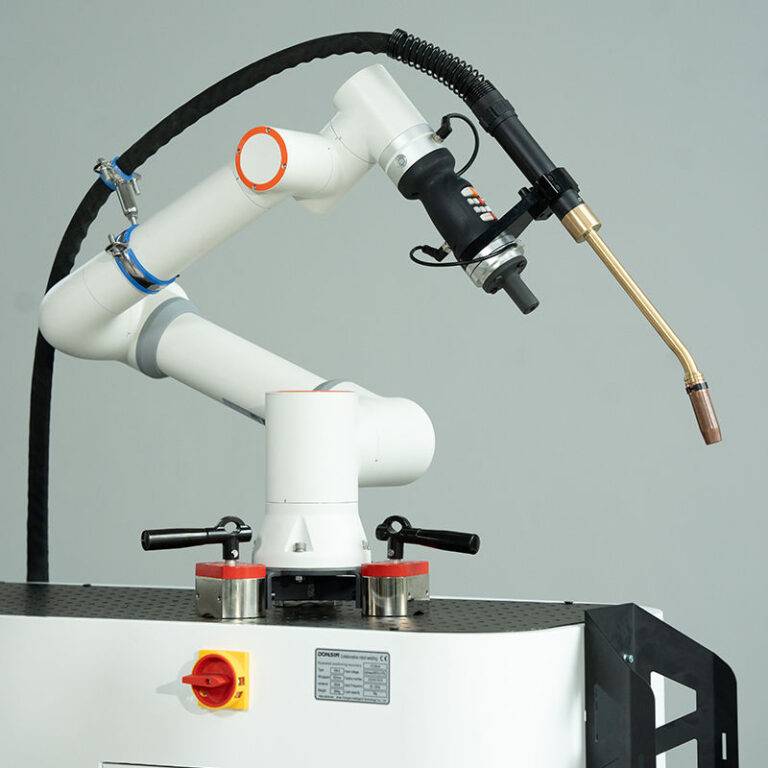
The core of the installation is a 6-axis high-speed Robotic Arm Welder mounted on a 10-meter linear track. In the context of Industrial Automation, the track itself is treated as a 7th axis, fully synchronized through the central controller. This allows for continuous welding on long-seam mild steel girders without the “stop-start” defects typical of manual or semi-automated processes.
The technical synergy here is found in the Tool Center Point (TCP) calibration. In Rotterdam, where we are dealing with heavy structural sections, the Robotic Arm Welder utilizes laser-touch sensing to find the groove orientation. The Industrial Automation software then adjusts the weld path in real-time, compensating for any thermal distortion that occurs during the Mild Steel welding process. This “search and track” capability is what separates modern robotic systems from legacy automated ‘hard-tooling’.
2.2 Communication Protocols and Control Logic
Field observation revealed that the handshake between the CMT power source and the robotic controller occurs over a dedicated EtherCAT bridge. This reduces latency to sub-5 milliseconds. For Mild Steel welding, this speed is critical during the CMT process, where the wire is physically retracted upon short-circuit detection. If the Industrial Automation sequence lags, the droplet detachment becomes inconsistent, leading to increased spatter—the very issue CMT is designed to eliminate.
3.0 Technical Analysis: Mild Steel Welding Performance
3.1 Metallurgy and Heat Input
Our primary material for this project is S355J2+N mild steel. The challenge with Mild Steel welding in heavy sections (15mm to 25mm) is managing the Heat Affected Zone (HAZ). Traditional MIG/MAG processes often result in excessive grain growth in the HAZ, reducing the toughness required for North Sea offshore applications.
The Precision CMT Robotic Arm Welder utilizes a modified dip-transfer process. By integrating the wire feed unit directly onto the robot’s “forearm,” the Industrial Automation system can oscillate the wire at frequencies up to 70Hz. This mechanical retraction aids in droplet detachment at near-zero current. The result is a significantly colder weld pool. During our Rotterdam tests, we recorded a 25% reduction in total heat input compared to manual pulsed-spray transfer, while maintaining full fusion at the root.
3.2 Shielding Gas Dynamics in Coastal Environments
One specific “lesson learned” in the Rotterdam workshop was the impact of cross-drafts on the Robotic Arm Welder. Mild steel is highly susceptible to porosity when the shielding gas (82% Argon / 18% CO2) is compromised. Even within a sheltered facility near the Waalhaven, the sheer scale of the Industrial Automation cells often creates internal wind tunnels. We had to implement localized “gas shielding curtains” on the robot head to ensure that the Mild Steel welding arc remained stable at travel speeds exceeding 800mm/min.
4.0 Industrial Automation: The Workflow Efficiency
4.1 Cycle Time and Duty Cycle Optimization
Before the introduction of the Robotic Arm Welder, the manual duty cycle for a standard 6-meter fillet weld was approximately 35%. The welder required breaks, repositioning, and slag cleaning. Under the Industrial Automation regime, the duty cycle has increased to 85%. The only downtime recorded is for wire spool changes and nozzle cleaning, which is handled by an automated reaming station integrated into the robot’s workspace.
Table 1: Comparative Performance Metrics (Rotterdam Facility)
- Manual Welding (Mild Steel): 12m per shift / 4% rework rate.
- Robotic Arm Welder (CMT): 48m per shift / 0.5% rework rate.
4.2 Sensor Integration and Error Handling
The Industrial Automation suite includes an upstream laser profile scanner. Before the Robotic Arm Welder strikes an arc, the scanner maps the joint geometry. If the gap exceeds 2.0mm—a common occurrence in heavy Mild Steel welding—the automation controller automatically switches the welding parameters to a “bridge-gap” schedule. This prevents burn-through and ensures structural integrity without manual intervention.
5.0 Practical Field Observations and Lessons Learned
5.1 Wire Feed Consistency
A recurring issue we faced during the first week in Rotterdam was “micro-slippage” in the wire drive rolls. Because the CMT process relies on rapid back-and-forth movement of the wire, the tension must be calibrated far more precisely than in standard Industrial Automation setups. We learned that using a matte-finish mild steel wire provided better “grip” for the robotic drive units compared to high-gloss copper-coated wires, which tended to flake and clog the liner.
5.2 The “Grounding” Factor
In large-scale Mild Steel welding, the return current path (grounding) is often overlooked. With a high-speed Robotic Arm Welder, inconsistent grounding caused “arc blow,” where the arc would deflect away from the joint. We solved this by installing dual-rotary grounding clamps on the workpiece positioner, integrated into the Industrial Automation safety circuit to ensure the robot cannot start unless a low-impedance ground is confirmed.
5.3 Maintenance of the Robotic Arm Welder
The saline environment of Rotterdam necessitates a more aggressive maintenance schedule for the robotic joints. We observed fine salt particulate buildup on the Axis 2 and Axis 3 seals. Our recommendation is a weekly pressurized air cleaning and the use of anti-static covers. While the Industrial Automation system is robust, the precision of the Robotic Arm Welder depends on the friction-free movement of these joints.
6.0 Quality Assurance and Compliance
6.1 Non-Destructive Testing (NDT) Results
The welds produced by the CMT Robotic Arm Welder underwent 100% Ultrasonic Testing (UT) and Magnetic Particle Inspection (MPI). In Mild Steel welding, the most common failures are lack of side-wall fusion or cold laps. The CMT’s ability to maintain a consistent arc length, managed by the Industrial Automation feedback loop, resulted in a 99.5% pass rate. The few failures were traced back to “tack welds” performed manually that were too large for the robot to consume smoothly.
6.2 Documentation and Digital Twins
A significant advantage of Industrial Automation in our Rotterdam operations is the data logging capability. For every meter of Mild Steel welding, the system logs voltage, current, wire feed speed, and gas flow. This “Digital Birth Certificate” for each component is now a requirement for our North Sea clients, providing a level of traceability that manual welding simply cannot match.
7.0 Conclusion and Recommendations
The deployment of the Precision CMT Robotic Arm Welder in Rotterdam has proven that Industrial Automation is not merely about speed; it is about controlling the variables that lead to failure in Mild Steel welding. The CMT process, specifically, offers a metallurgical advantage by lowering heat input, which is vital for preserving the mechanical properties of S355 steel.
Key Recommendations for Future Rollouts:
- Environmental Control: Install high-volume extraction combined with localized shielding to combat the Rotterdam humidity.
- Consumable Selection: Standardize on non-copper-coated wires to reduce robotic liner wear.
- Upstream Precision: Improve the fit-up of mild steel parts; while the Robotic Arm Welder can compensate for gaps, it performs best when the tolerance is held within +/- 1.0mm.
The synergy of these technologies has effectively doubled our output capacity while significantly reducing the cost of quality. We are prepared to move to Phase 2, which involves the integration of twin-wire robotic systems for even heavier deposition rates.
Report Compiled By:
Senior Welding Engineer, Rotterdam Division
Specialization: Automated Joining Technologies & Heavy Structural Metallurgy