Field Report: Deployment of Collaborative Arc Welding Systems for Multi-pass Carbon Steel Fabrication
1. Project Overview and Site Conditions
This report details the technical deployment and operational integration of a Collaborative Arc Welding System at a heavy-duty structural steel facility in the Amata City Industrial Estate, Chonburi, Thailand. The primary objective was to transition manual Carbon Steel welding operations for thick-plate pressure vessels and structural beams into a semi-autonomous workflow using Automated Welding technology.
The Chonburi environment presents specific metallurgical and mechanical challenges. Ambient humidity levels exceeding 85% and temperatures frequently peaking at 38°C necessitated strict controls over consumables and interpass temperature management. The focus was on multi-pass fillet and groove welds on ASTM A36 and A516 Grade 70 carbon steel, ranging from 15mm to 40mm in thickness.
2. Technical Specifications of the Collaborative Arc Welding System
Unlike traditional industrial robots that require extensive safety cell infrastructure, the Collaborative Arc Welding System (hereafter referred to as the “cobot welder”) was selected for its footprint-to-capability ratio. In the Chonburi workshop, floor space is at a premium. The system utilized a 6-axis collaborative arm integrated with a high-performance pulsed-GMAW (Gas Metal Arc Welding) power source.
Hardware and Interface Integration
The synergy between the cobot’s lead-through programming and the power source’s digital communication protocol allowed for real-time adjustment of arc parameters. For Carbon Steel welding, we utilized an 80/20 Argon/CO2 shielding gas mix. The system was equipped with a “through-arc” seam tracking sensor, essential for multi-pass applications where thermal distortion can shift the joint geometry between the root and cap passes.
3. Implementation of Automated Welding in Multi-pass Scenarios
The core technical hurdle in Automated Welding for heavy sections is the management of the weld pool in successive layers. For a 25mm V-groove joint, we programmed a 7-pass sequence.
The Root and Hot Pass Strategy
The root pass was executed using a short-circuit transfer mode to ensure full penetration without burn-through. A major lesson learned here was the sensitivity of the Collaborative Arc Welding System to wire-stick-out (CTWD). Even a 2mm variance caused by inconsistent plate tacking resulted in arc instability. We moved to a rigid fixture strategy to maintain the precision required for the automated pathing.
Filling and Capping Layers
For the fill passes, we transitioned to spray transfer to maximize deposition rates. The Automated Welding logic handled the oscillation (weaving) patterns. We found that a “Crescent” weave pattern at 2.5Hz provided the best sidewall fusion on Carbon Steel welding, preventing the “cold lap” issues common in manual operations when the welder fatigues in the Chonburi heat.
4. Synergy: Collaborative Systems vs. Traditional Automation
In the Chonburi context, the synergy between “Collaborative” and “Automated” means the human welder becomes a “Cell Manager.” While the Collaborative Arc Welding System handles the high-heat, high-arc-time tasks, the technician prepares the next joint or performs interpass cleaning.
The Automated Welding aspect ensures that the travel speed remains constant at 350mm/min for the fill passes—a speed difficult for manual welders to maintain consistently over a 10-hour shift in Thai humidity. This consistency directly correlates to a uniform Heat Affected Zone (HAZ), which is critical for the impact toughness of the carbon steel components being fabricated.
5. Site-Specific Challenges in Chonburi, Thailand
Atmospheric Management
The high humidity in Chonburi is a precursor to hydrogen-induced cracking in Carbon Steel welding. We observed that even with “low hydrogen” wires, moisture condensation on the cold steel plates during the morning shift was problematic. The Automated Welding system cannot “see” moisture. We implemented a mandatory pre-heat protocol (to 110°C) using induction heating blankets before the Collaborative Arc Welding System was engaged.
Power Grid Stability
Industrial estates in Chonburi can experience voltage fluctuations during peak afternoon loads. Since the Collaborative Arc Welding System relies on sensitive encoders and digital signal processing, we installed a dedicated power conditioner. Without this, we noted “stuttering” in the Automated Welding path, which created slag inclusions in the multi-pass stack.
6. Metallurgical Results and Weld Quality
Post-weld visual inspection and Ultrasonic Testing (UT) showed a significant reduction in defect rates compared to manual labor.
- Porosity: Reduced by 85% due to consistent gas lens coverage maintained by the robot arm.
- Slag Inclusions: Eliminated through precise interpass pathing that ensured optimal “toe” wetting.
- Deposition Efficiency: Increased by 35% as the Automated Welding system operates at a higher duty cycle (approximately 75%) compared to manual welding (30-40%).
7. Lessons Learned and Senior Engineering Observations
The “Black Box” Trap
One primary lesson is that a Collaborative Arc Welding System is not a “set and forget” tool. The Automated Welding software for multi-pass assumes a perfect joint. In reality, Carbon Steel welding involves plate mill scale, varied gap widths, and heat distortion. The operator must be trained to adjust “On-the-Fly” offsets. In Chonburi, we found that training local welders to become “Cobot Technicians” was more effective than bringing in external robotics programmers who lacked “dirt-under-the-fingernails” welding experience.
Interpass Temperature Control
In a multi-pass Automated Welding setup, the system can move from Pass 3 to Pass 4 faster than the steel can dissipate heat. On Carbon Steel welding (specifically A516), exceeding an interpass temperature of 250°C degrades the grain structure. We had to program “Cooling Dwells” into the Collaborative Arc Welding System logic, allowing the sensor to trigger the next pass only when the thermocouple confirmed the steel had cooled to the appropriate range.
Wire Feeding Issues
The Collaborative Arc Welding System often uses a conduit that is longer than manual torches. We experienced bird-nesting at the feeder due to the soft copper coating on some locally sourced carbon steel wires. Switching to a high-quality, matte-finish wire with a specialized drum-feed system solved the feeding friction, which is vital for the 24/7 Automated Welding cycles we aimed for.
8. Economic and Safety Impact
The ROI for the Chonburi facility is projected at 14 months. Beyond the Automated Welding throughput, the safety benefits are paramount. The Collaborative Arc Welding System keeps the welder away from the plume of hexavalent chromium (if welding stainless) and the intense UV radiation of high-amperage Carbon Steel welding. In the cramped, hot conditions of a Thailand workshop, reducing the physical strain on the workforce is not just ethical; it is a business necessity to prevent turnover.
9. Conclusion
The integration of the Collaborative Arc Welding System in Chonburi proves that Automated Welding is no longer reserved for high-volume automotive lines. By applying these systems to heavy Carbon Steel welding, we have achieved a level of multi-pass consistency that manual processes cannot match. The success of such a deployment hinges not on the robot itself, but on the engineer’s ability to adapt the automation to the environmental realities of the Thai industrial landscape. Future phases will look into integrating AI-based vision systems to further automate the “root-gap” compensation in real-time.
Report Prepared By:
Senior Welding Engineer, Field Operations
Chonburi, Thailand
-


LT240S tube laser cutting machine
-
LT120S tube laser cutting machine
-
Sale

Tank Fillet Welding Machine
Original price was: $1,000.00.$900.00Current price is: $900.00. -
Sale

MAK100 tube laser cutting machine
Original price was: $5,500.00.$5,000.00Current price is: $5,000.00. -

portable plasma air cutting machine
$1,200.00 -

2in1 fiber laser cutting machine
-

Air cooling Laser welding machine
-

HF h beam laser cutting machine
-

LT240 laser cutting machine
-

Laser welding machine
-


Cobot Welding Station
-

Gantry welding robot solution
-

Tracked Wheeled AGV Welding robot
-

LFH6020 Fiber laser cutting machine
-
LFP6020
-

robotic welidng machine
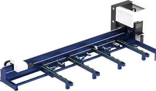
Advanced Fiber Laser Tube Processing Technology
Our CNC Fiber Laser Tube Cutting systems revolutionize metal fabrication by integrating high-precision cutting, punching, and profiling into a single automated workflow. Designed for versatility, this technology handles a wide array of profiles including Round, Square, Rectangular, and Oval tubes, as well as complex L-shaped and U-shaped channels.
- Precision Punching: High-speed hole punching with micron-level accuracy, eliminating the need for mechanical drilling or die-stamping.
- Complex Profiling: Advanced 3D pathing allows for intricate interlocking joints and specialized notch cuts, ideal for structural frames.
- High Material Efficiency: Intelligent nesting software minimizes scrap, reducing raw material costs across large production runs.
- Clean Finish: Delivers oxide-free, burr-free edges that require zero secondary grinding before welding.

Seamlessly processing multiple profiles with consistent precision.
Global Delivery & Logistics



From our high-tech manufacturing facility directly to your global site. PCL WeldCut ensures secure packaging, professional handling, and reliable international logistics to safeguard your equipment throughout the entire journey.