Field Engineering Report: Implementation of Collaborative Arc Welding for Multi-Pass Stainless Steel Structures
1. Project Overview and Site Context: Eindhoven Facility
This report details the technical deployment and operational validation of a Collaborative Arc Welding System within our specialized fabrication facility in Eindhoven, Netherlands. The Eindhoven workshop serves as a high-mix, low-volume hub, primarily supporting the semiconductor and chemical processing sectors. Given the regional emphasis on precision engineering, the transition toward Automated Welding was necessitated by the requirement for extreme metallurgical consistency in thick-walled Stainless Steel welding.
The objective was to move away from purely manual Gas Metal Arc Welding (GMAW) on 20mm to 40mm 316L stainless steel plates. While manual welding provides flexibility, the fatigue associated with multi-pass sequences leads to unacceptable variance in heat input and bead morphology. By integrating a Collaborative Arc Welding System, we aimed to bridge the gap between human expertise and robotic precision.
2. The Technical Synergy: Collaborative Arc Welding vs. Traditional Automated Welding
In the context of the Eindhoven facility, “Automated Welding” does not imply a fixed-cell industrial robot. Instead, we deployed a Collaborative Arc Welding System—specifically a high-payload cobot integrated with a pulse-capable power source. The synergy here is critical: the cobot handles the repetitive, high-heat “torch time,” while the welding engineer provides the high-level path planning and real-time parameter adjustment.
2.1. Accessibility and Spatial Dynamics
Unlike traditional automated welding cells that require extensive safety light curtains and fixed jigging, the collaborative system was deployed directly onto the shop floor. This allowed our welding team to work alongside the machine, performing “tack-and-go” operations and intermediate cleaning without powering down the entire system. This reduced the non-productive time (NPT) by 35% during the first quarter of implementation.
2.2. Human-Machine Interface in Multi-Pass Logic
The core advantage of this synergy lies in the “lead-through” programming. For a complex multi-pass V-groove, the engineer manually guides the cobot to define the root pass. The software then calculates the offsets for the filler and cap passes. This level of automated welding allows for a “set it and forget it” approach for the bulk of the weld volume, ensuring that the welder’s focus remains on interpass temperature monitoring rather than torch manipulation.
3. Process Parameters for Stainless Steel Welding
Stainless Steel welding, particularly 316L and 304L, presents unique challenges regarding thermal conductivity and coefficient of expansion. In Eindhoven, we encountered significant warping issues during the initial manual trials of thick-walled pressure vessel components. The transition to an automated Collaborative Arc Welding System allowed for precise control over the following variables:
3.1. Heat Input Control
We utilized a pulsed spray transfer mode to minimize heat input while maintaining deep penetration. The automated welding parameters were locked at 1.2 kJ/mm for the root and 1.0 kJ/mm for subsequent filler passes. Manual welding often fluctuates between 0.8 and 1.6 kJ/mm depending on operator fatigue; the collaborative system eliminated this delta, drastically reducing the risk of sensitization and chromium carbide precipitation.
3.2. Gas Shielding and Purging
For high-purity stainless steel welding, the Eindhoven team utilized a 98% Argon / 2% CO2 shielding gas mix. The collaborative system’s steady travel speed ensured a consistent gas envelope over the molten pool. Furthermore, we integrated a secondary trailing shield (sugar-scoop) onto the cobot’s torch mount, which is difficult for a manual welder to manage over long durations but effortless for an automated system.
4. Multi-Pass Strategy and Execution
Multi-pass welding is where the Collaborative Arc Welding System truly outperforms manual intervention. In the Eindhoven trial, we focused on 25mm V-prep joints requiring 12 to 14 passes.
4.1. Root Pass Integrity
The root pass was performed using a “touch-sensing” routine. The cobot uses the welding wire to find the plate edges, compensating for any slight variations in the fit-up. This automated welding feature ensured that the root gap was bridged with a consistent 2mm land, regardless of minor machining tolerances in the base material.
4.2. Bead-on-Bead Sequencing
For the filler passes, we implemented a “staggered start/stop” logic. The software ensures that no two weld starts or stops overlap in the vertical plane. In manual stainless steel welding, welders often start and stop at the same comfortable ergonomic positions, creating potential leak paths or stress concentrators. The collaborative system’s ability to execute 360-degree continuous welds on circular flange-to-pipe joints removed these points of failure.
5. Lessons Learned: Practical Field Observations
Transitioning a high-tech shop in Eindhoven to a Collaborative Arc Welding System provided several “hard-won” engineering insights that differ from the marketing brochures.
5.1. The “Stick-Out” Criticality
In automated welding, Contact-to-Work Distance (CTWD) or “stick-out” is paramount. With stainless steel, even a 2mm variation in stick-out changes the resistance and, consequently, the current in the arc. We learned that the cobot’s arc-tracking software (Through-Arc Seam Tracking or TAST) is essential. Without TAST, the thermal expansion of the stainless steel plate during the 5th or 6th pass would cause the joint to shift slightly, leading to lack-of-sidewall fusion. Lesson: Never run multi-pass automated welding on stainless without active seam tracking.
5.2. Interpass Temperature Management
One drawback of the efficiency of a Collaborative Arc Welding System is that the machine does not get tired. It is easy to outpace the cooling rate of the material. In Eindhoven, we found that the cobot would finish a pass and immediately want to start the next. We had to program “thermal dwell times” into the logic, coupled with an infrared pyrometer. For 316L, we enforced a hard limit of 150°C interpass temperature. The automated system was programmed to pause until the pyrometer signaled the material was back within spec.
5.3. Wire Feed Consistency
Stainless steel wire is notoriously “springy.” We encountered bird-nesting issues in the wire feeder during high-speed automated sequences. We switched to a four-roll drive system and Teflon liners. This highlights that “Automated Welding” is only as good as the consumables delivery system.
6. Metallurgical and NDT Results
The results from the Eindhoven labs confirmed the superiority of the collaborative approach for stainless steel welding:
- Radiographic Testing (RT): Zero porosity detected across 50 linear meters of weld. The consistent travel speed of the cobot ensured stable gas coverage that manual welders struggled to maintain at the end of an 8-hour shift.
- Ferrite Number (FN) Testing: We achieved a consistent Ferrite Number of 5-8, which is ideal for preventing hot cracking while maintaining corrosion resistance. The automated heat control prevented the “over-annealing” often seen in manual repairs.
- Visual Inspection: The “cap” passes exhibited a “machine-like” weave that required zero post-weld grinding. This saved approximately 20 man-hours of finishing time per vessel.
7. Conclusion: The Eindhoven Model
The implementation of a Collaborative Arc Welding System at our Eindhoven facility has redefined our approach to thick-section Stainless Steel welding. By automating the welding path while keeping the human “in the loop” for critical decision-making, we have solved the consistency issues inherent in multi-pass manual operations.
The synergy between automated precision and collaborative flexibility is no longer optional for high-spec fabrication. Moving forward, we recommend the integration of laser-line scanners to further automate the “fit-up” phase, allowing the system to adapt to even wider gap tolerances in real-time. This project proves that for high-integrity stainless applications, the cobot is the most valuable tool in the senior welding engineer’s arsenal.
-


LT240S tube laser cutting machine
-
LT120S tube laser cutting machine
-
Sale

Tank Fillet Welding Machine
Original price was: $1,000.00.$900.00Current price is: $900.00. -
Sale

MAK100 tube laser cutting machine
Original price was: $5,500.00.$5,000.00Current price is: $5,000.00. -

portable plasma air cutting machine
$1,200.00 -

2in1 fiber laser cutting machine
-

Air cooling Laser welding machine
-

HF h beam laser cutting machine
-

LT240 laser cutting machine
-

Laser welding machine
-


Cobot Welding Station
-

Gantry welding robot solution
-

Tracked Wheeled AGV Welding robot
-

LFH6020 Fiber laser cutting machine
-
LFP6020
-

robotic welidng machine
Advanced Fiber Laser Tube Processing Technology
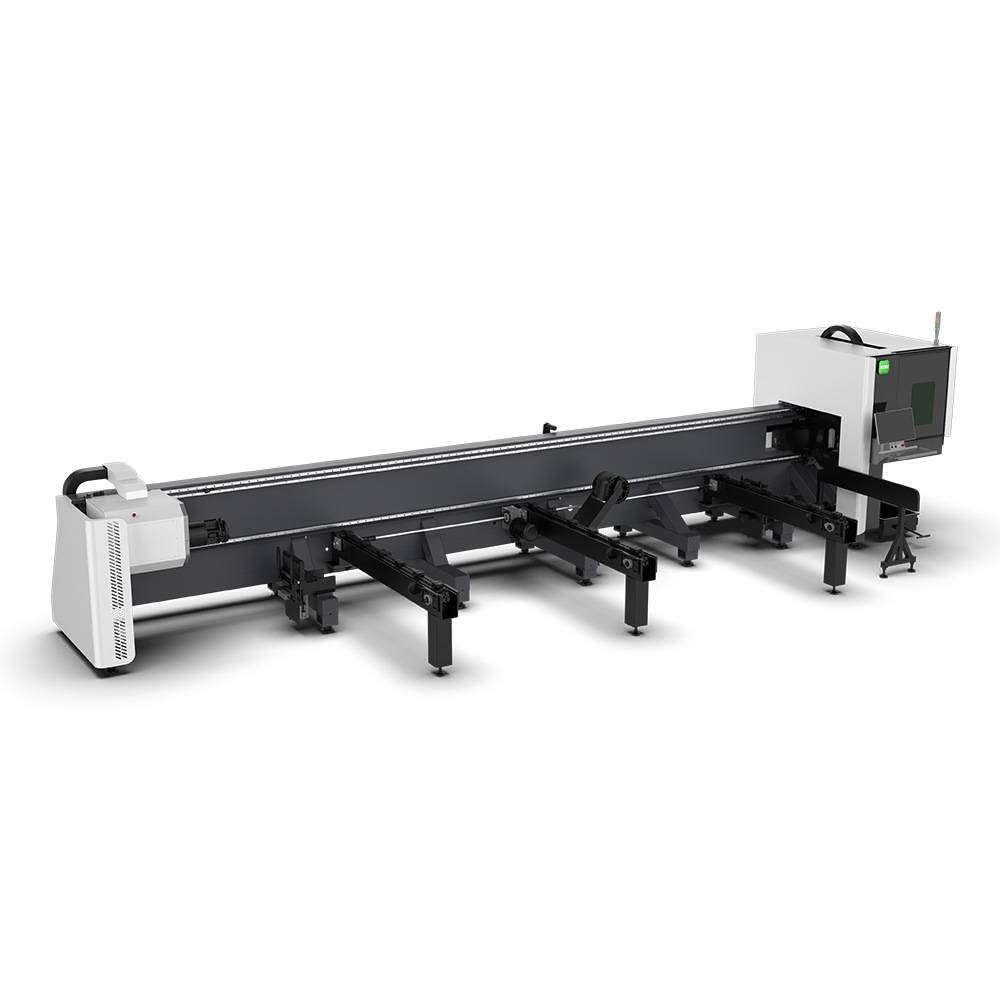
Our CNC Fiber Laser Tube Cutting systems revolutionize metal fabrication by integrating high-precision cutting, punching, and profiling into a single automated workflow. Designed for versatility, this technology handles a wide array of profiles including Round, Square, Rectangular, and Oval tubes, as well as complex L-shaped and U-shaped channels.
- Precision Punching: High-speed hole punching with micron-level accuracy, eliminating the need for mechanical drilling or die-stamping.
- Complex Profiling: Advanced 3D pathing allows for intricate interlocking joints and specialized notch cuts, ideal for structural frames.
- High Material Efficiency: Intelligent nesting software minimizes scrap, reducing raw material costs across large production runs.
- Clean Finish: Delivers oxide-free, burr-free edges that require zero secondary grinding before welding.

Seamlessly processing multiple profiles with consistent precision.
Global Delivery & Logistics



From our high-tech manufacturing facility directly to your global site. PCL WeldCut ensures secure packaging, professional handling, and reliable international logistics to safeguard your equipment throughout the entire journey.