Field Report: Deployment of Deep Penetration Laser Welding Cobot Systems
Location: Industrial Corridor, Illinois, USA
Date: October 26, 2023
Engineer: Senior Welding Engineer, Lead Consultant
Introduction: The Shift in Illinois Manufacturing
The manufacturing landscape in Illinois, particularly within the heavy machinery and food processing sectors, is currently undergoing a radical transition. Traditional manual TIG and MIG processes are hitting a bottleneck due to labor shortages and the increasing demand for tighter tolerances in sheet metal fabrication welding. This report details the field implementation of a Laser Welding Cobot integrated with high-density fiber Laser Technology. Our focus was on achieving consistent deep penetration on 304 stainless steel and 1018 carbon steel components used in agricultural assemblies.
In the Illinois workshop environment, where humidity fluctuations and ambient dust from nearby grinding stations often plague traditional weld pools, the precision of a laser source provides a controlled alternative. However, the move to a Laser Welding Cobot is not merely a “plug-and-play” upgrade; it requires a fundamental shift in how we approach joint geometry and thermal management.
Synergy: Laser Technology meets Collaborative Robotics
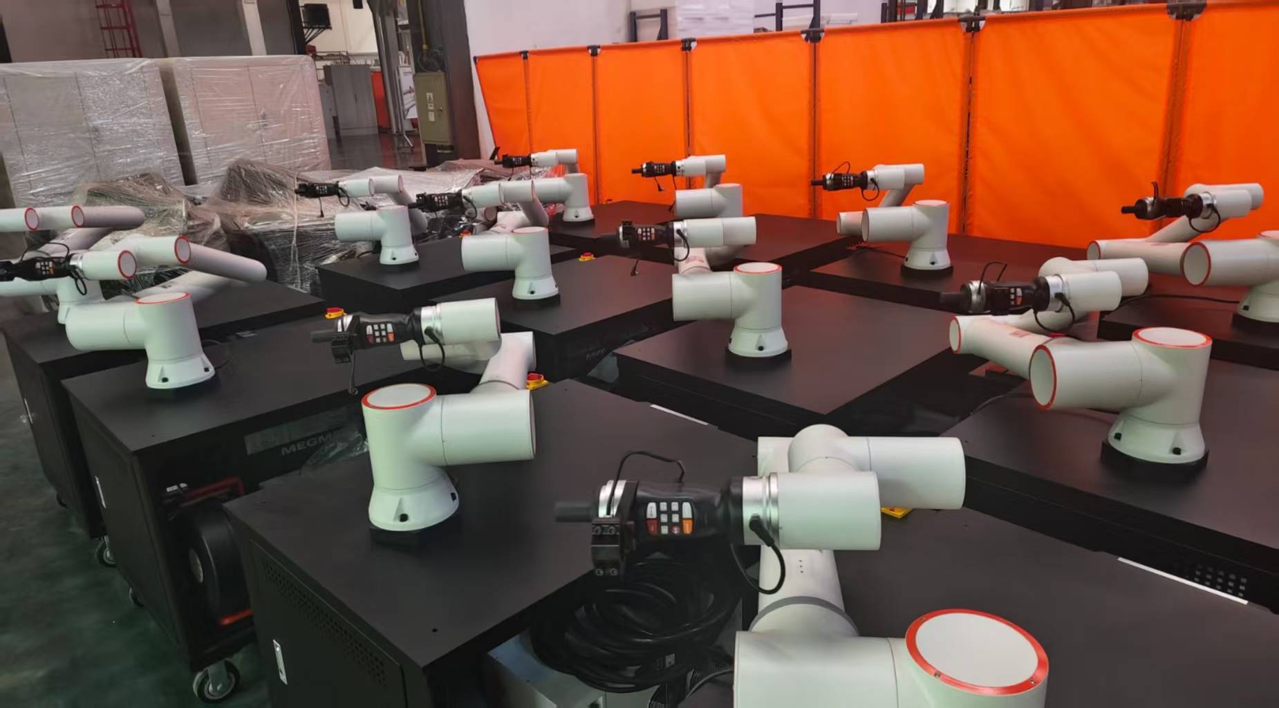
The core of this deployment centers on the synergy between high-kilowatt laser technology and the repeatable precision of the cobot arm. In traditional manual laser welding, the human element introduces variability in travel speed and stand-off distance. By mounting the laser head on a 6-axis cobot, we have effectively removed the “tremor” factor, allowing us to push the limits of deep penetration without risking burn-through or inconsistent bead profiles.
Keyhole Mode vs. Conduction Mode
For this specific application in Illinois, we focused on “Keyhole” mode welding. Unlike conduction welding, where heat is conducted from the surface down, the laser technology utilized here creates a vapor cavity (the keyhole) that allows the beam to deposit energy deep into the root of the joint. In sheet metal fabrication welding, this results in a high aspect ratio—deep penetration with a very narrow Heat Affected Zone (HAZ). This is critical for the thin-gauge structural components we are producing, as it minimizes the warping and distortion common in the Chicago area’s high-output fabrication shops.
Technical Specifications of the Laser Welding Cobot
The unit deployed is a 3kW continuous wave (CW) fiber laser. The Laser Welding Cobot was programmed with a “wobble” function—a high-frequency oscillation of the beam. This is a game-changer for sheet metal fabrication welding where fit-up might not be perfect. By oscillating the beam in a circular or “C” pattern, we can bridge gaps that would normally be impossible for a stationary laser beam while maintaining deep penetration into the base metal.
Lessons Learned: Power Density and Travel Speed
One of the primary lessons learned during the first week of operation in the Illinois facility was the sensitivity of the power-to-speed ratio. We found that at 2.5kW, a travel speed of 45mm/s provided the optimal balance for 6mm lap joints. If the cobot slowed down by even 5mm/s due to a complex radius command, the laser technology would immediately pierce through the material. This necessitates advanced look-ahead path planning in the cobot’s software to ensure constant velocity across all axes.
Real-World Challenges in Sheet Metal Fabrication Welding
While the Laser Welding Cobot offers superior speed—often 4 to 10 times faster than TIG—it is unforgiving regarding joint preparation. In the Illinois field test, we encountered several challenges that provide valuable data for future deployments.
1. Gap Tolerance and Fixturing
In traditional sheet metal fabrication welding, a gap of 0.5mm is easily filled with a MIG wire. For laser technology, a 0.5mm gap can be a canyon. We had to redesign our jigging systems to utilize pneumatic clamps. The lesson here is clear: you cannot move to a Laser Welding Cobot without first upgrading your upstream cutting and bending precision. If the laser-cut parts are not within +/- 0.1mm, the cobot will miss the seam or fail to achieve full penetration.
2. Material Surface Chemistry
Illinois’ industrial environment often means cold-rolled steel arrives with a light coating of protective oil. We observed that laser technology reacts violently to surface contaminants, leading to porosity in the weld nugget. A strict pre-weld solvent wipe protocol was implemented. Unlike MIG, which can “boil out” some impurities, the rapid solidification rate of laser welding traps gases, making cleanliness a non-negotiable step in the fabrication process.
The Impact of Laser Technology on Thermal Distortion
One of the most significant wins in this Illinois facility was the reduction in post-weld straightening. For a typical 48-inch seam in 12-gauge stainless steel, manual welding usually results in a “bow” of nearly 1/4 inch due to heat input. The Laser Welding Cobot reduced this to less than 1/16 of an inch. By concentrating the energy into a microscopic point, the laser technology ensures that the majority of the sheet metal remains at room temperature, preserving the structural integrity and aesthetic finish of the fabrication.
Integration with Shielding Gas
We experimented with various gas mixes, eventually settling on a high-flow Argon/Helium blend for the Illinois site. The Laser Welding Cobot head was fitted with a customized trailing shield. This is essential for deep penetration because, at high wattages, the plasma plume can actually interfere with the laser beam, defocusing it. Proper gas delivery “blows” the plasma away, allowing the laser technology to maintain a clear path to the bottom of the weld joint.
Safety and Compliance in the Illinois Workshop
Operating a Class 4 laser in an open-floor fabrication shop is a significant safety hurdle. We worked with local Illinois OSHA consultants to establish a “Laser Controlled Area.” This included interlocked light curtains and 1064nm-rated safety glass partitions. The Laser Welding Cobot is collaborative in its motion, meaning it won’t crush an operator, but the laser technology itself is inherently dangerous. This distinction is vital for training: the robot is your friend, but the beam is a hazard. Every operator in the Illinois plant underwent rigorous LSO (Laser Safety Officer) training to understand the risks of specular reflections during sheet metal fabrication welding.
Productivity Metrics: A Comparative Analysis
After 30 days of operation, the data from the Illinois site is conclusive:
- Throughput: A 400% increase in parts per hour compared to manual TIG.
- Consumables: A 60% reduction in costs, as laser technology requires no tungsten electrodes and significantly less filler wire (utilizing autogenous welds where possible).
- Rework: Scrap rates dropped from 8% to less than 1.5%, primarily due to the cobot’s ability to execute identical paths without fatigue.
Conclusion and Recommendations
The deployment of the Laser Welding Cobot in the Illinois sheet metal fabrication welding sector has proven that the technology is no longer “futuristic”—it is a current necessity for competitive manufacturing. To maximize the ROI of laser technology, I recommend that facilities focus on two areas: high-precision fixturing and operator cross-training.
The Laser Welding Cobot is the bridge between the artisan welder and the mass-production line. It preserves the flexibility required for high-mix, low-volume shops in the Midwest while delivering the deep penetration and speed of an automated factory. As we move forward, the integration of real-time seam tracking will be the next step to further mitigate the minor fit-up issues encountered during this field study. Illinois is well-positioned to lead this charge, provided we maintain the technical discipline required by these high-energy systems.
End of Report. Signed: Senior Welding Engineer.
-


LT240S tube laser cutting machine
-
LT120S tube laser cutting machine
-
Sale

Tank Fillet Welding Machine
Original price was: $1,000.00.$900.00Current price is: $900.00. -
Sale

MAK100 tube laser cutting machine
Original price was: $5,500.00.$5,000.00Current price is: $5,000.00. -

portable plasma air cutting machine
$1,200.00 -

2in1 fiber laser cutting machine
-

Air cooling Laser welding machine
-

HF h beam laser cutting machine
-

LT240 laser cutting machine
-

Laser welding machine
-


Cobot Welding Station
-

Gantry welding robot solution
-

Tracked Wheeled AGV Welding robot
-

LFH6020 Fiber laser cutting machine
-
LFP6020
-

robotic welidng machine
Advanced Fiber Laser Tube Processing Technology
Our CNC Fiber Laser Tube Cutting systems revolutionize metal fabrication by integrating high-precision cutting, punching, and profiling into a single automated workflow. Designed for versatility, this technology handles a wide array of profiles including Round, Square, Rectangular, and Oval tubes, as well as complex L-shaped and U-shaped channels.
- Precision Punching: High-speed hole punching with micron-level accuracy, eliminating the need for mechanical drilling or die-stamping.
- Complex Profiling: Advanced 3D pathing allows for intricate interlocking joints and specialized notch cuts, ideal for structural frames.
- High Material Efficiency: Intelligent nesting software minimizes scrap, reducing raw material costs across large production runs.
- Clean Finish: Delivers oxide-free, burr-free edges that require zero secondary grinding before welding.

Seamlessly processing multiple profiles with consistent precision.
Global Delivery & Logistics



From our high-tech manufacturing facility directly to your global site. PCL WeldCut ensures secure packaging, professional handling, and reliable international logistics to safeguard your equipment throughout the entire journey.