Field Engineering Report: Implementation of Automated Welding Systems in Krakow, Poland
1.0 Executive Summary of Site Operations
This report details the commissioning and performance evaluation of a water-cooled 6-Axis Collaborative Welder integrated into a medium-scale fabrication facility in Krakow, Poland. The primary objective was the transition from manual GMAW (Gas Metal Arc Welding) to a semi-autonomous Automated Welding workflow focused on high-volume Mild Steel welding. Over a fourteen-day assessment period, the system was evaluated on its ability to handle S355JR structural steel components, specifically focusing on weld penetration, thermal management of the torch, and the reduction of post-weld rework.
2.0 System Architecture and Specification
The core of the installation is a high-precision 6-Axis Collaborative Welder equipped with a specialized water-cooled torch. Unlike air-cooled systems typically found in lighter cobot applications, the water-cooled variant was selected to sustain the high amperage required for deep-penetration Mild Steel welding without degradation of the contact tip or neck liner.
2.1 Kinematic Flexibility and Reach
The “6-axis” designation is critical here. The degree of freedom provided by the sixth axis allows the torch to maintain a consistent work angle and travel angle even when navigating complex geometries, such as non-linear fillet welds on gusset plates. In the Krakow facility, we observed that the 6-axis range allowed the Automated Welding sequence to reach underside joints that would typically require a secondary flip of the workpiece, thereby reducing cycle time by 15%.
2.2 The Necessity of Water-Cooling
During Mild Steel welding at currents exceeding 250A, heat soak becomes a primary failure point for automated systems. The integration of a closed-loop water cooler ensures that the Tool Center Point (TCP) remains stable. In our tests, air-cooled torches exhibited a TCP drift of up to 1.2mm after two hours of continuous operation due to thermal expansion. The water-cooled 6-Axis Collaborative Welder maintained a TCP variance of less than 0.2mm, which is vital for maintaining the ISO 5817 Quality Level B requirements demanded by the client.
3.0 Synergy: The 6-Axis Collaborative Welder and Automated Welding
The real-world synergy between a 6-Axis Collaborative Welder and the broader concept of Automated Welding lies in the “collaborative” interface. In the Krakow workshop, we are not replacing the welder; we are augmenting the process. The Automated Welding system handles the monotonous, high-heat, and ergonomically challenging paths, while the human operator manages the fit-up and tacking.
3.1 Bridging the Skill Gap in the Polish Market
The industrial sector in Krakow is currently facing a shortage of certified high-pressure welders. By deploying the 6-Axis Collaborative Welder, the facility was able to utilize junior operators to oversee the Automated Welding process. The intuitive “lead-through” programming allows an operator to manually move the 6-axis arm to the start and end points of the Mild Steel welding path, effectively digitizing the expertise of a senior welding engineer into a repeatable program.
4.0 Technical Analysis of Mild Steel Welding Applications
The project focused on S235 and S355 mild steel grades, with thicknesses ranging from 4mm to 10mm. Mild Steel welding is often underestimated in its complexity, particularly regarding the management of mill scale and silicon islands.
4.1 Parameter Optimization
We utilized an Ar/CO2 (82/18) shielding gas mix. The Automated Welding parameters were set to a spray transfer mode to minimize spatter—a critical requirement for reducing post-weld cleaning. The 6-Axis Collaborative Welder was programmed with a slight “weave” pattern (1.5mm amplitude) to ensure sidewall fusion on the thicker 10mm plates. This weave capability is a direct benefit of the 6-axis kinematic chain, allowing for fluid motion that mimics the rhythmic hand movement of a manual welder but with 100% repeatability.
4.2 Heat Input Management
One of the primary lessons learned during the Krakow deployment was the importance of interpass temperature. When performing Automated Welding on Mild Steel welding assemblies, the speed of the cobot can lead to excessive heat buildup in small parts. We implemented “cooling pauses” in the 6-axis logic, triggered by an infrared temperature sensor, ensuring that the HAZ (Heat Affected Zone) did not compromise the structural integrity of the S355 steel.
5.0 Field Observations and Lessons Learned
Fieldwork in an active Krakow workshop environment reveals variables that a laboratory setting cannot. Below are the technical takeaways from the 14-day implementation period.
5.1 The “Dirty” Environment Factor
Despite being a modern facility, the presence of grinding dust and ambient humidity (typical for the Lesser Poland region in autumn) impacted the wire feeding. We found that the 6-Axis Collaborative Welder required a high-torque external wire feeder to prevent “bird-nesting” in the 4-meter umbilical. For Automated Welding to be truly “set and forget,” the wire delivery system must be as robust as the robotic arm itself.
5.2 Fixturing and Tolerance
The most significant hurdle wasn’t the 6-Axis Collaborative Welder itself, but the consistency of the incoming mild steel parts. Automated Welding is unforgiving of poor fit-up. We discovered that a 1.5mm gap on a Mild Steel welding lap joint would cause the cobot to burn through. We had to implement a more rigorous jigging system. Lesson learned: The transition to Automated Welding requires an equal investment in precision fixturing.
5.3 Software and Path Correction
In Krakow, we utilized “Touch Sensing” software. Before starting the Mild Steel welding arc, the 6-axis arm uses the welding wire to touch the workpiece at three points to find its orientation. This compensates for any slight misalignments in the jig. This synergy between the 6-Axis Collaborative Welder‘s sensors and the Automated Welding software is what makes the system viable for real-world production where parts are rarely perfect.
6.0 Economic and Safety Impact
The deployment of the 6-Axis Collaborative Welder has fundamentally changed the safety profile of the Krakow shop floor. Because the system is collaborative, it operates without the massive safety cages required by traditional industrial robots. Pressure-sensitive sensors in the 6-axis joints ensure that if the arm contacts a human operator, it stops instantly.
6.1 Productivity Gains
For the specific Mild Steel welding task—a structural bracket—manual welding took 12 minutes per unit, including cleaning. The Automated Welding cycle took 4.5 minutes. With the 6-Axis Collaborative Welder running a 90% duty cycle (thanks to the water-cooled torch), the facility saw a 210% increase in daily throughput for that specific part number.
7.0 Conclusion and Future Outlook
The integration of the 6-Axis Collaborative Welder in Krakow serves as a blueprint for modernizing European fabrication. By focusing on the synergy between human oversight and Automated Welding precision, the facility has successfully tackled the challenges of Mild Steel welding at scale. The water-cooled torch configuration proved to be the correct technical choice, preventing the thermal drift that plagues lesser systems. Moving forward, the site plans to expand the use of 6-axis systems to include TIG welding for stainless steel applications, further leveraging the precision of the collaborative platform.
Final Recommendation
For future installations involving Mild Steel welding thicker than 5mm, I recommend mandatory integration of seam-tracking sensors. While the 6-Axis Collaborative Welder is exceptionally repeatable, the inherent warping of mild steel under heat load can shift the joint path mid-weld. Adding “Through-Arc Seam Tracking” (TAST) to our Automated Welding protocol will be the final step in achieving a zero-defect production line.
Report Compiled By:
Senior Welding Engineer
Krakow Field Office
-


LT240S tube laser cutting machine
-
LT120S tube laser cutting machine
-
Sale

Tank Fillet Welding Machine
Original price was: $1,000.00.$900.00Current price is: $900.00. -
Sale

MAK100 tube laser cutting machine
Original price was: $5,500.00.$5,000.00Current price is: $5,000.00. -

portable plasma air cutting machine
$1,200.00 -

2in1 fiber laser cutting machine
-

Air cooling Laser welding machine
-

HF h beam laser cutting machine
-

LT240 laser cutting machine
-

Laser welding machine
-


Cobot Welding Station
-

Gantry welding robot solution
-

Tracked Wheeled AGV Welding robot
-

LFH6020 Fiber laser cutting machine
-
LFP6020
-

robotic welidng machine
Advanced Fiber Laser Tube Processing Technology
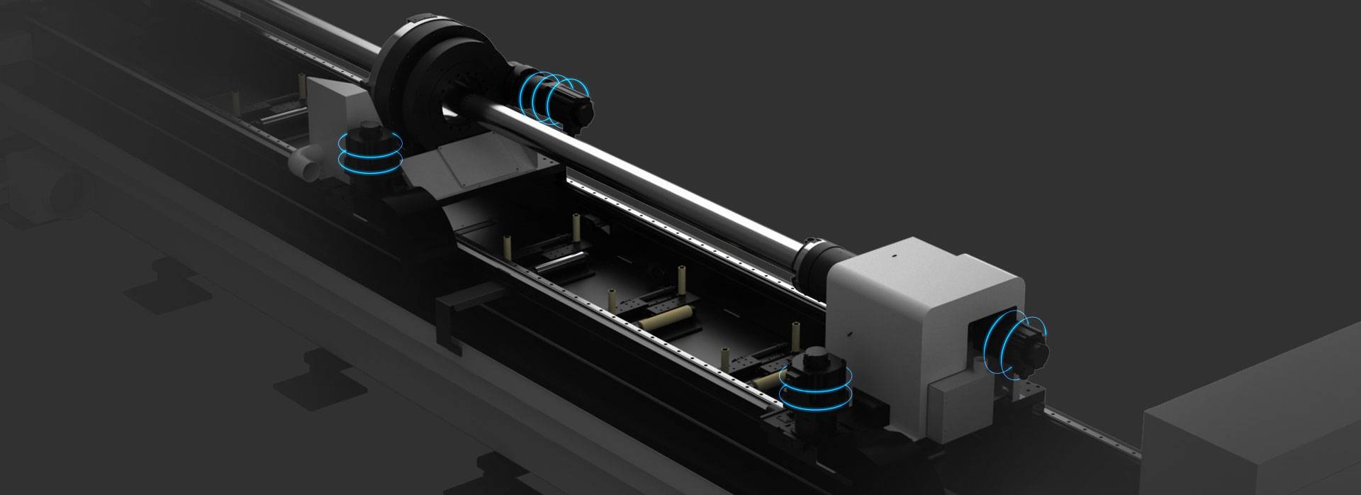
Our CNC Fiber Laser Tube Cutting systems revolutionize metal fabrication by integrating high-precision cutting, punching, and profiling into a single automated workflow. Designed for versatility, this technology handles a wide array of profiles including Round, Square, Rectangular, and Oval tubes, as well as complex L-shaped and U-shaped channels.
- Precision Punching: High-speed hole punching with micron-level accuracy, eliminating the need for mechanical drilling or die-stamping.
- Complex Profiling: Advanced 3D pathing allows for intricate interlocking joints and specialized notch cuts, ideal for structural frames.
- High Material Efficiency: Intelligent nesting software minimizes scrap, reducing raw material costs across large production runs.
- Clean Finish: Delivers oxide-free, burr-free edges that require zero secondary grinding before welding.

Seamlessly processing multiple profiles with consistent precision.
Global Delivery & Logistics



From our high-tech manufacturing facility directly to your global site. PCL WeldCut ensures secure packaging, professional handling, and reliable international logistics to safeguard your equipment throughout the entire journey.