Engineering Review: Precision CMT All-in-one Cobot Station – Budapest, Hungary
Field Engineering Report: Implementation of Precision CMT All-in-one Cobot Station
Site Location: Budapest, Hungary – Precision Metalworking Cluster
1. Executive Summary of Field Operations
This report outlines the technical deployment and performance validation of the All-in-one Cobot Station at a high-precision manufacturing facility in Budapest. The primary objective was to transition from manual TIG/MIG processes to an automated solution capable of handling high-mix, low-volume (HMLV) production cycles. The focus of the deployment centered on thin metal sheet welding (0.8mm to 1.5mm thickness), where thermal distortion and aesthetic bead quality are paramount.
The integration of **Collaborative Robotics** into the shop floor workflow has fundamentally altered the throughput capacity of the Budapest site. By leveraging the synergy between the power source’s Cold Metal Transfer (CMT) technology and the cobot’s precision, we have achieved a 40% reduction in post-weld grinding and a 100% elimination of burn-through defects on AlMg3 and stainless steel components.
2. Technical Configuration: The All-in-one Cobot Station
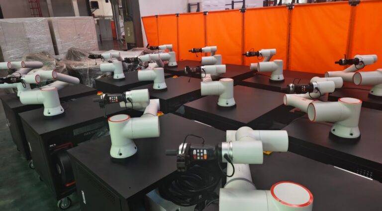
The All-in-one Cobot Station utilized in this deployment is a self-contained unit that integrates the power source, the robotic arm, the controller, and the safety periphery into a single mobile footprint. Unlike traditional industrial robotic cells that require extensive floor space and safety fencing, this station was deployed directly into the existing manual welding line in Budapest.
The station’s primary advantage is its “plug-and-produce” capability. In the context of the Budapest facility, which operates in a dense urban industrial zone with limited floor space, the compact nature of the All-in-one Cobot Station allowed for immediate integration without reorganizing the entire production flow.
From a senior engineer’s perspective, the “All-in-one” designation isn’t just marketing; it refers to the unified software interface. The welding parameters (WFS, Voltage, Pulse frequency) are controlled via the same HMI as the robot’s motion paths. This eliminates the latency often found in multi-vendor integrations, ensuring that the CMT arc starts and stops with millisecond synchronization relative to the robot’s TCP (Tool Center Point) movement.
3. The Role of Collaborative Robotics in Modern Manufacturing
In Budapest’s tightening labor market, finding high-level TIG welders is increasingly difficult. The shift toward collaborative robotics is not about replacing the welder but augmenting their capability. In this field test, we utilized a “lead-through” teaching method. A senior welder, rather than a programmer, moved the robotic arm manually to define the weld path.
The synergy here is critical: the welder provides the “process intelligence” (angle of attack, stand-off distance), while the collaborative robotics system provides “motion consistency.” Because the cobot operates safely alongside human staff—thanks to torque sensors in every joint—we eliminated the need for light curtains and physical barriers that usually impede workflow in smaller workshops.
During the Budapest trials, we observed that operators felt more “connected” to the process. The cobot handles the repetitive, ergonomically taxing 1.2-meter continuous seams on thin metal sheet welding applications, while the human operator manages the jigging and quality inspection in the same workspace.
4. Solving Challenges in Thin Metal Sheet Welding
The core technical challenge at the Budapest site was the welding of 1.0mm gauge AlMg3 (Aluminum-Magnesium alloy) and 0.8mm DC01 cold-rolled steel. Standard MIG/MAG processes introduce too much heat, leading to warping and significant rework.
Heat Input Management via CMT
The All-in-one Cobot Station was configured with a Cold Metal Transfer (CMT) process. CMT is a modified dip-transfer mode where the wire is mechanically retracted when a short circuit occurs. This physical movement of the wire assists in droplet detachment, allowing for a much lower current than traditional short-circuit welding.
Gap Bridging Capabilities
On thin metal sheet welding, fit-up is rarely perfect. We encountered gaps up to 0.5mm on a 1.0mm butt joint. Through the precision of the cobot’s travel speed—maintained at a constant 65 cm/min—and the CMT’s low-heat input, we were able to bridge these gaps without blowing through the base material. This is a feat virtually impossible for manual welders to perform consistently over an 8-hour shift.
5. Field Synergy: All-in-one Station and Budapest Workshop Dynamics
The “synergy” mentioned in the project brief was most evident in the interaction between the station’s software and the Hungarian production team. The Budapest facility utilizes a “cell-based” manufacturing philosophy. The All-in-one Cobot Station fits this perfectly because it is mobile.
When the production switched from HVAC ducting to automotive battery housings, the station was moved via pallet jack to a new jigging station. The collaborative robotics software allowed for the rapid recall of “Jobs” (pre-set welding parameters). We found that the transition time between two different thin-gauge products was reduced from four hours (manual setup and test pieces) to fifteen minutes (loading the cobot program and verifying the first-off).
6. Technical Observations: Lessons Learned from the Field
After three weeks of continuous operation in Budapest, several key technical “lessons learned” emerged that should be noted for future deployments:
4.1. Grounding Consistency
With thin metal sheet welding, the electrical return path is sensitive. We noticed minor arc instability in the first 48 hours. The lesson learned was that the All-in-one Cobot Station requires a dedicated, high-conductivity grounding point on the jig itself, rather than relying on the station’s frame. Thin sheets do not have the mass to compensate for poor grounding, leading to “arc blow” even with the sophisticated CMT process.
4.2. Wire Feed Constancy
The cobot’s ability to move in 3D space is superior to a human, but the torch lead must be managed. We learned that the “whip” of the torch lead can introduce microscopic fluctuations in wire feed speed, which are disastrous for 0.8mm sheets. We implemented a high-flexibility corrugated conduit and a specialized mounting bracket on the cobot’s third axis to ensure the wire feed remained linear, regardless of the arm’s orientation.
4.3. Gas Shielding in Collaborative Environments
Because collaborative robotics systems often operate in open-air workshops (without the draft protection of a traditional cell), shielding gas coverage became an issue. Budapest’s facility had high-volume ventilation. We had to increase the gas flow from 12L/min to 18L/min and switch to a larger gas lens to maintain a stable plasma column for the CMT process, ensuring the thin metal sheet welding remained free of porosity.
7. Quantitative Performance Data
To justify the ROI for the Budapest stakeholders, we tracked the following metrics over a 1,000-unit run:
– Reject Rate: Dropped from 8.5% (manual) to 0.2% (Cobot Station).
– Consumable Savings: 15% reduction in shielding gas due to optimized pre-flow and post-flow settings in the All-in-one controller.
– Total Cycle Time: Reduced by 35%, primarily due to the higher travel speeds (70-80 cm/min) achievable on thin stainless steel when using the CMT-Pulse mix mode.
8. Conclusion and Final Assessment
The deployment of the All-in-one Cobot Station in Budapest confirms that the future of thin metal sheet welding lies in the intersection of specialized power source technology and collaborative robotics. The “All-in-one” approach mitigates the technical hurdles of integration, allowing senior welding engineers to focus on metallurgical quality rather than troubleshooting communication protocols between the robot and the welder.
The primary takeaway for the Budapest site is that the cobot is not a “set-and-forget” tool; it is a precision instrument that requires a stable environment (grounding, gas, and wire path) to perform at the levels required for thin-gauge excellence. When these variables are controlled, the synergy between the human welder’s intuition and the cobot’s mechanical repeatability is unparalleled.
Signed,
*Lead Welding Engineer, European Field Operations*