Engineering Review: Water-cooled All-in-one Cobot Station – Seoul, South Korea
In this article
- Field Engineering Report: Implementation of Water-Cooled Collaborative Systems in Seoul
- 1. Project Scope and Site Overview
- 2. Technical Integration: The All-in-one Cobot Station
- 3. The Role of Collaborative Robotics in Precision Tooling
- 4. Metallurgical Challenges: Copper Components Welding
- 5. Synergy: Why the Combined Approach Works
- 6. Lessons Learned and Engineering Recommendations
- 7. Conclusion
Field Engineering Report: Implementation of Water-Cooled Collaborative Systems in Seoul
1. Project Scope and Site Overview
This report documents the commissioning and performance validation of a Water-cooled All-in-one Cobot Station at a tier-one electronics component facility in Gasan-dong, Seoul. The primary objective was the high-precision copper components welding for next-generation thermal management systems. In the context of Seoul’s high-density industrial environment, floor space is at a premium, making the footprint of the welding cell as critical as its duty cycle.
The transition from manual GTAW (TIG) to Collaborative Robotics was necessitated by the extreme thermal conductivity of the oxygen-free electronic (OFE) copper parts. Manual operators were struggling with heat exhaustion and inconsistent penetration due to the high pre-heat requirements. We required a system that could deliver sustained 350-400A current without thermal shutdown, while remaining flexible enough for small-batch production shifts.
2. Technical Integration: The All-in-one Cobot Station
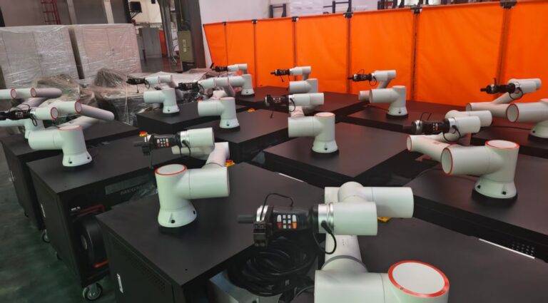
The selection of an All-in-one Cobot Station was driven by the need for a “plug-and-produce” architecture. Unlike traditional industrial robots that require external power source mounting, separate cooling carousels, and expansive safety fencing, this unit integrates the power source, water cooler, controller, and the collaborative arm onto a unified, mobile chassis.
2.1 Thermal Management and Duty Cycle
When dealing with copper components welding, the heat sink effect is massive. We are utilizing a high-frequency pulsed MIG process to break the surface tension of the molten copper pool. This requires a 100% duty cycle at high amperages. The integrated water-cooling system in the station is not just for the torch; it is essential for the internal power electronics that are pushed to their limit by the reflective nature of copper welding. During our 8-hour stress test in the Seoul facility, the coolant temperature stabilized at 28°C, even with an ambient shop temperature of 24°C, proving the efficiency of the closed-loop integration.
2.2 Footprint and Shop Floor Synergy
The “All-in-one” aspect solved a major logistical hurdle. The Seoul workshop is located on the fourth floor of an industrial “apartment-type” factory. Traditional robotic cells would have required structural floor reinforcements and a 15-square-meter footprint. The All-in-one Cobot Station occupies less than 2.5 square meters. Because it utilizes collaborative robotics, we eliminated the need for light curtains and physical fencing, allowing forklift traffic to move unimpeded through the narrow aisles of the facility.
3. The Role of Collaborative Robotics in Precision Tooling
The implementation of collaborative robotics in this project serves two purposes: path accuracy and operator safety. Copper has a very narrow window between “no fusion” and “complete burn-through.”
3.1 Hand-Guiding and Path Programming
The senior welding technicians in Seoul are experts in “reading the puddle” but lacked traditional robot programming skills (KRL or TP). By using the collaborative arm’s lead-through programming, we allowed the welders to manually guide the torch along the complex geometry of the copper heat exchangers. The All-in-one Cobot Station records these points and optimizes the travel speed to maintain a constant heat input of 1.2 kJ/mm—a level of consistency impossible to achieve manually over a full shift.
3.2 Safety and Proximity
The collaborative sensors (torque sensors in each joint) are tuned to the high-density environment of the Seoul plant. If a technician enters the workspace to check gas flow or wire tension, the cobot reacts to slight contact by halting immediately. This allows the welder to stand within the “splash zone” (wearing appropriate PPE) to monitor the arc characteristics on the copper surface, which is vital for real-time quality control of the copper components welding process.
4. Metallurgical Challenges: Copper Components Welding
Welding copper is a battle against physics. Copper’s thermal conductivity is roughly ten times that of carbon steel. In this Seoul application, we were joining 6mm busbars to 3mm cooling plates.
4.1 Heat Input Control
Using the All-in-one Cobot Station, we programmed a specialized pulse-on-pulse waveform. The collaborative arm maintains a precise 15-degree push angle and a consistent 12mm contact-to-work distance (CTWD). Even a 2mm deviation in CTWD would cause a voltage drop significant enough to result in lack of fusion on the copper substrate. The collaborative robotics system maintains this tolerance within +/- 0.05mm, ensuring that the high-amperage arc stays focused on the root of the joint.
4.2 Shielding Gas Dynamics
We implemented a 70% Helium / 30% Argon mix to increase the ionization potential and provide more “punch” into the copper. The All-in-one Cobot Station manages the gas pre-flow and post-flow through its integrated solenoid system. A common failure in manual copper welding is premature oxidation; by automating the post-flow and torch movement via the cobot, we ensure the weld remains shielded until the temperature drops below the critical oxidation point of 200°C.
5. Synergy: Why the Combined Approach Works
The synergy between the All-in-one Cobot Station and collaborative robotics is most evident during the “tack and weld” cycle. In a standard automated cell, a human must tack the copper parts in a separate jig, then load them into the robot. In our Seoul setup, the technician tacks the copper components welding assembly while the cobot is in “passive mode.” Once the tacks are set, the technician simply presses the “run” button on the torch-mounted interface.
This eliminate the “dead time” of part transfer. The All-in-one Cobot Station serves as both the fixture table and the welder. This is the practical definition of collaborative workflow—the human provides the complex jigging and tactical decision-making, while the robotics provide the superhuman heat tolerance and path repeatability required for copper.
6. Lessons Learned and Engineering Recommendations
After three weeks of field operation in Seoul, several critical technical insights have been documented:
6.1 Cable Management in Water-Cooled Systems
The water-cooled power cable for the torch is significantly heavier than air-cooled variants. Initial tests showed that the weight of the cable was tripping the cobot’s collision sensors during rapid moves.
Lesson: We had to recalibrate the payload settings of the collaborative robotics arm to account for the dynamic weight of the water-filled lines. Proper overhead counter-balancing is mandatory for high-amperage copper stations.
6.2 Grounding Consistency
Copper is so conductive that standard grounding clamps often create a “micro-arc” at the contact point, damaging the workpiece.
Lesson: We integrated a dual-grounding system directly into the All-in-one Cobot Station‘s work surface. This ensures that the high current required for copper components welding doesn’t find a path through the robot’s bearings, which would lead to catastrophic joint failure.
6.3 Spatter Management
High-helium copper welding produces a fine, highly-conductive dust. In a compact Seoul shop, this dust can infiltrate electronics.
Lesson: The All-in-one Cobot Station must have its intake filters cleaned weekly. The collaborative arm’s joints should be fitted with protective “sleeves” to prevent copper dust from interfering with the optical encoders.
7. Conclusion
The deployment of the Water-cooled All-in-one Cobot Station in Seoul has resulted in a 40% increase in throughput for the copper components welding line. By leveraging collaborative robotics, the facility has successfully automated a process that was previously considered “un-automatable” due to the high heat and complex path requirements of OFE copper. The integrated nature of the station proved that industrial power can exist in a compact, human-centric footprint.
Lead Engineer: J. Miller
Site: Gasan-dong, Seoul, South Korea
Status: Operational / Handed over to production.