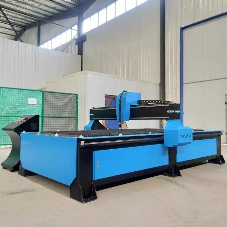
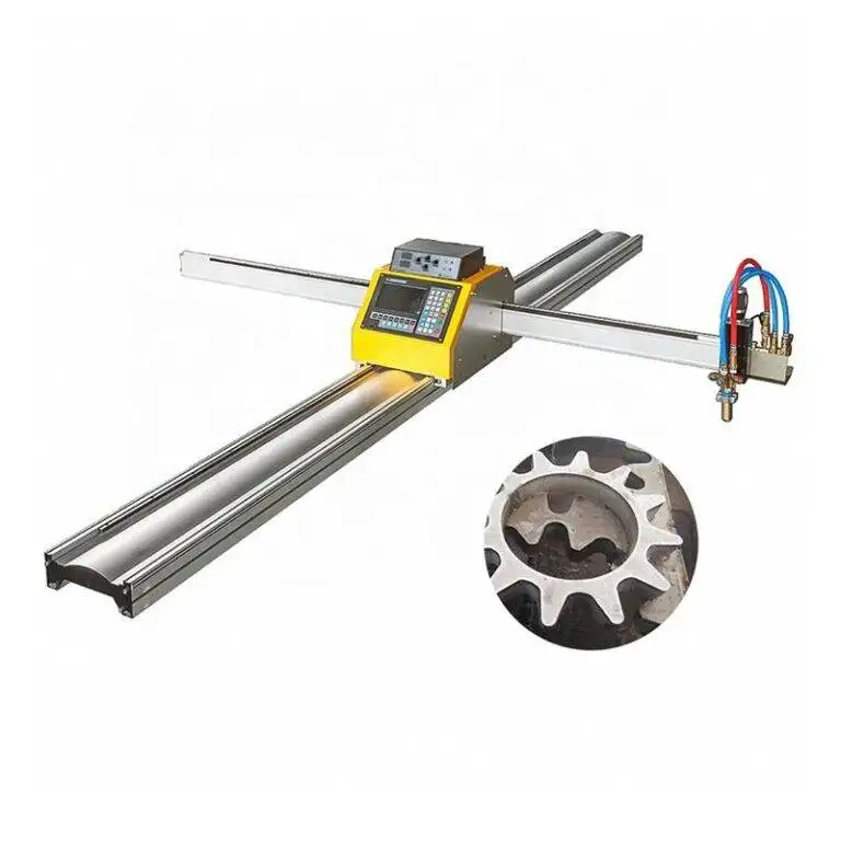
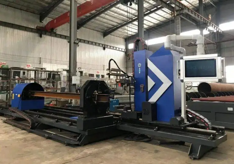
Beam Processing Center with Offline Programming for for Bridge Trusses
In this article
- Automating Bridge Truss Fabrication through Plasma Processing
- Precision at Scale: Intersection Accuracy in Complex Geometries
- Geometric Tolerance and Kerf Compensation
- Advanced Beveling for Structural Integrity
- Optimizing Weld Prep and Heat Input
- Offline Programming: The Digital Backbone
- Collision Avoidance and Path Optimization
- Operational Efficiency and Low Maintenance Architecture
- Simplified Consumable Management
- Material Handling and Flow Logic
- Conclusion: The Future of Infrastructure Fabrication
Automating Bridge Truss Fabrication through Plasma Processing
Bridge truss manufacturing demands high dimensional fidelity and structural integrity. The transition from manual layout and mechanical sawing to a centralized Beam Processing Center equipped with robotic Plasma Cutting represents a significant shift in industrial throughput. In bridge engineering, where H-beams and structural channels form the backbone of the infrastructure, the precision of every cut directly impacts the fatigue life and load distribution of the final assembly. The primary challenge lies in the complex intersections where diagonal members meet chords. Traditional methods often result in gaps that necessitate excessive filler material, whereas automated plasma systems provide the geometric accuracy required for tight-fit joints.
Precision at Scale: Intersection Accuracy in Complex Geometries
The core requirement for Bridge Trusses is the seamless fitment of web members and chords. Robotic plasma cutting centers utilize 6-axis or 8-axis movement to navigate the flanges and webs of H-beams. This multi-axis capability is essential for creating complex “fish-mouth” cuts or intricate copes that match the profile of the mating member. Intersection accuracy is not merely a matter of aesthetic fit; it is a structural necessity. When bridge components are assembled, even a 2mm deviation across a large-span truss can lead to significant alignment issues during site erection.
Geometric Tolerance and Kerf Compensation
Modern plasma power sources, integrated with CNC controllers, manage real-time kerf compensation. As the plasma torch moves, the system calculates the width of the material removed by the ionized gas stream. For H-beams, which often possess inherent mill tolerances and slight deviations in flange parallelism, the processing center utilizes touch probes or laser sensors to map the actual profile of the steel before the first arc is struck. This “measure-and-cut” cycle ensures that the theoretical CAD model is adapted to the physical reality of the steel beam, maintaining tolerances within fractions of a millimeter.
Advanced Beveling for Structural Integrity
Bridge trusses frequently require Complete Joint Penetration (CJP) welds to handle dynamic loads. Preparing these joints involves complex beveling on the edges of the H-beam flanges and webs. A robotic beam processing center excels here by executing variable angle bevels—V, Y, K, and X profiles—in a single pass. Unlike manual oxy-fuel cutting or mechanical grinding, robotic plasma beveling produces a consistent land and groove angle across the entire length of the cut.
Optimizing Weld Prep and Heat Input
The metallurgical properties of bridge-grade steel (such as A709 or S355) are sensitive to heat input. High-definition plasma systems minimize the Heat-Affected Zone (HAZ) by maintaining high travel speeds and precise voltage control. By automating the beveling process, the facility ensures that the joint geometry is optimized for the specific welding procedure specification (WPS). This precision reduces the volume of weld metal required and minimizes the risk of lack-of-fusion defects at the root of the joint.
Offline Programming: The Digital Backbone
The efficiency of a beam processing center is determined largely by its uptime. Manual “teach-pendant” programming is non-viable for bridge trusses, where every project may feature unique beam lengths and connection details. Offline programming (OLP) allows engineers to generate cutting paths directly from 3D BIM or CAD models (such as Tekla or SDS/2 files). This process happens while the machine is actively cutting another part, effectively decoupling programming time from production time.
Collision Avoidance and Path Optimization
OLP software simulates the entire cutting sequence within a virtual environment. This simulation is critical for H-beam processing because the robotic arm must often reach deep into the “pocket” between flanges to cut the web. The software identifies potential collisions between the torch head and the beam flanges, automatically recalculating the approach angle. Furthermore, path optimization algorithms minimize the “torch-off” time, ensuring the machine follows the most efficient trajectory between different cut features, such as bolt holes and coping zones.
Operational Efficiency and Low Maintenance Architecture
From an industrial engineering perspective, the choice of plasma over mechanical alternatives like drills and saws is driven by operational continuity. Mechanical systems involve high-wear components—drill bits, saw blades, and coolant systems—that require frequent replacement and monitoring. In contrast, plasma cutting systems for H-beams are characterized by low mechanical contact. The torch remains at a stand-off distance from the material, reducing the mechanical stress on the robotic gantry or arm.
Simplified Consumable Management
The primary maintenance requirements for a plasma-based center are limited to the torch consumables (nozzles, electrodes, and swirl rings) and the dust collection system. In a high-volume bridge fabrication plant, these parts can be swapped in minutes, compared to the hours required to replace or sharpen large-scale saw blades. Furthermore, the absence of cutting fluids and coolants simplifies the workspace, as the process is entirely dry. This cleanliness is particularly beneficial for downstream processes like painting or galvanizing, where residual oils can cause coating failures.
Material Handling and Flow Logic
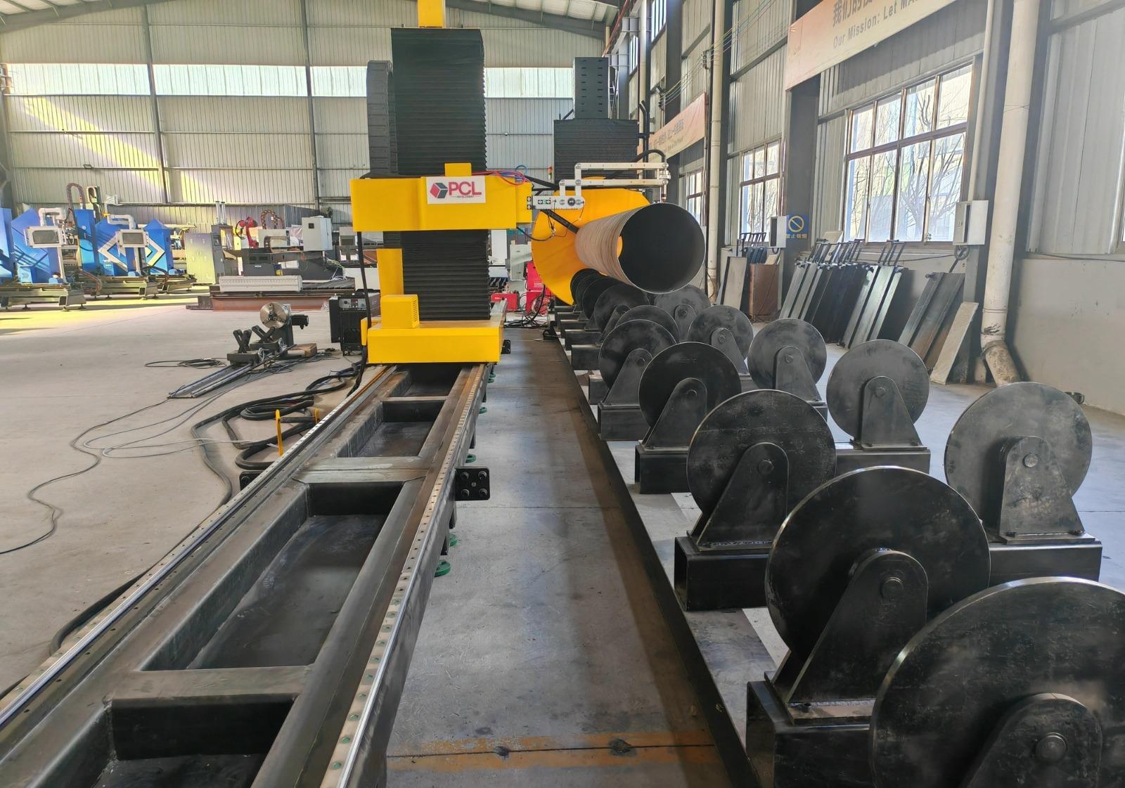
A beam processing center is an integrated ecosystem. The workflow begins with an infeed conveyor that measures the raw beam length using high-resolution encoders. Once the beam is positioned, hydraulic clamps secure it to eliminate vibration. The robotic plasma unit then executes all necessary operations—bolt holes, copes, bevels, and marking—without the beam needing to be moved to different workstations. Once completed, the beam moves to the outfeed zone, pre-marked with part numbers and layout lines for subsequent assembly.
Automated Layout Marking
One often overlooked benefit of the plasma center is its ability to perform layout marking. By using the plasma arc at a low amperage, the robot can etch assembly marks directly onto the chord members. This indicates exactly where the web members should be placed, eliminating the need for manual tape measurements and significantly reducing the margin for human error during the fit-up phase of truss assembly.
Conclusion: The Future of Infrastructure Fabrication
The adoption of robotic plasma technology in bridge truss fabrication addresses the dual pressures of labor shortages and increasing technical complexity. By focusing on intersection accuracy and leveraging offline programming, fabricators can achieve a level of consistency that manual methods cannot replicate. The low maintenance profile of plasma systems, combined with their ability to handle heavy-section H-beams, positions these centers as the definitive solution for modern infrastructure projects. As bridge designs continue to push the boundaries of span and geometry, the precision of the beam processing center remains the foundational element of structural safety and manufacturing efficiency.