Optimizing LNG Infrastructure Fabrication via Plasma Technology
Liquefied Natural Gas (LNG) projects demand unprecedented levels of structural integrity due to the extreme thermal stresses and corrosive environments associated with liquefaction and regasification terminals. For the industrial engineer, the challenge lies in the mass production of complex structural steel components—primarily H-beams, channels, and heavy-wall piping—that meet stringent American Petroleum Institute (API) and ASME standards. The shift toward Plasma Cutting Machine systems equipped with sophisticated offline programming (OLP) has become a technical necessity to maintain throughput without sacrificing dimensional tolerance.
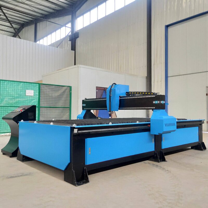
Unlike traditional mechanical methods, modern plasma systems utilize high-energy ionized gas to execute complex geometries in heavy-gauge carbon and stainless steel. In the context of LNG projects, where modular construction is the industry standard, the ability to produce repeatable, accurate components for skid-mounted equipment and pipe racks is the primary driver of operational efficiency.
3D Intersection Accuracy in Complex Structural Joints
One of the most significant hurdles in LNG structural fabrication is the precision required for beam-to-beam and pipe-to-beam intersections. LNG modules often feature intricate bracing systems designed to withstand seismic loads and cryogenic pipe expansion. Standard manual layout and cutting are insufficient for these requirements.
Mathematical Precision in Multi-Axis Cutting
High-definition plasma systems, integrated with 5-axis or 6-axis robotic arms, allow for the execution of complex intersection accuracy. This is particularly vital when cutting “fish-mouth” joints or coping H-beams to fit snuggly against circular hollow sections (CHS). The OLP software calculates the exact intersection curve, accounting for the kerf width and the torch angle. This ensures that the fit-up gap is minimized, typically held to tolerances within ±0.5mm. By achieving this level of accuracy, the subsequent welding process is stabilized, reducing the volume of filler metal required and minimizing the risk of heat-induced distortion in the structural frame.
Eliminating Manual Layout Errors
In a traditional shop environment, marking complex intersections on a large H-beam is a time-intensive process prone to human error. Offline programming eliminates this step by extracting coordinates directly from the TEKLA or Revit BIM model. The plasma torch follows a digitally verified path, ensuring that every bolt hole, slot, and cope is positioned with absolute geometric fidelity relative to the beam’s center line. This “first-time-right” approach is critical for LNG Projects where material lead times are long and scrap costs are high.
Low Maintenance Requirements for H-Beam Processing
Industrial engineers focus heavily on Total Productive Maintenance (TPM) and equipment uptime. In the harsh, dust-heavy environments of heavy fabrication yards, the mechanical robustness of the cutting system is paramount. Plasma technology offers a distinct advantage in the processing of heavy H-beams and structural profiles.
Durability of Plasma Components
The H-beam low maintenance profile of plasma systems stems from the rugged nature of the torch assembly and the absence of sensitive optical components. Plasma torches are designed to operate in high-duty cycle environments where metallic dust and slag are prevalent. Unlike other thermal cutting methods that require pristine environments, plasma systems utilize robust consumables—nozzles, electrodes, and swirl rings—that can be replaced in seconds without specialized recalibration. This resilience ensures that the machine remains operational during double-shift schedules common in large-scale LNG modular builds.
Simplified Motion Control and Slag Management
Modern H-beam plasma lines are engineered with integrated slag collection systems and self-cleaning drive racks. Because the cutting process is non-contact, there is no mechanical stress on the gantry or robotic arm, reducing wear on bearings and motors. Furthermore, the use of dry-extraction filtration systems specifically designed for plasma fumes keeps the workspace clean and protects the electronic control units from conductive dust, further extending the Mean Time Between Failures (MTBF).
Advanced Beveling for Weld Preparation
In LNG projects, the majority of structural connections and pipe joins require full-penetration welds. This necessitates precise beveling of the plate and beam edges. Plasma cutting machines equipped with a rotating tilt head allow for beveling to be performed simultaneously with the profile cutting, eliminating secondary grinding or milling operations.
A/B Axis Beveling Configurations
The ability to perform V, X, Y, and K-cuts on H-beams and thick plates is a core requirement for LNG fabrication. Through offline programming, the plasma torch can vary its angle dynamically during a cut. For example, when cutting a web opening in an H-beam, the machine can transition from a 90-degree square cut to a 45-degree bevel seamlessly. This ensures that the weld preparation is uniform across the entire geometry, which is essential for automated welding processes that follow the cutting stage. Uniform bevels lead to consistent weld penetration and better performance under the non-destructive testing (NDT) protocols required for LNG infrastructure.
Controlling the Heat Affected Zone (HAZ)
While plasma is a thermal process, high-definition (HD) plasma systems use constrained arcs and high gas pressures to narrow the kerf and localize the heat. This is particularly important for the high-strength steels used in LNG support structures. By maintaining a narrow HAZ, the metallurgical properties of the H-beam remain intact, ensuring that the structural component maintains its designed tensile strength and impact resistance at low temperatures.
The Role of Offline Programming (OLP) in Production Flow
The transition from manual machine operation to OLP is the single greatest contributor to productivity in modern fabrication. Offline programming allows engineers to program the cutting sequences on a remote workstation while the plasma machine is actively cutting another part. This decouples the programming time from the machine time, effectively pushing machine utilization toward 85-90%.
Direct CAD-to-CAM Integration
In LNG projects involving thousands of unique structural members, manually programming each part is impossible. OLP software imports 3D XML or DSTV files directly from the design engineering team. The software automatically recognizes the beam profile, identifies the required cuts, and generates the G-code. It also performs collision detection, ensuring the torch head does not interfere with the flanges of the H-beam during complex beveling maneuvers. This digital workflow ensures that the physical part produced in the shop is a 1:1 match with the digital twin in the project model.
Nesting Efficiency and Material Management
Beyond geometry, OLP provides sophisticated nesting algorithms for plates and beams. For LNG projects, where specialized alloys may be used, maximizing material yield is essential. The software can nest parts across multiple lengths of H-beams, accounting for the kerf and the clamp zones of the machine, significantly reducing drop-off waste.
Conclusion: Engineering ROI through Plasma Systems
For the LNG sector, the decision to implement a plasma cutting machine with Offline Programming is driven by the need for scalability, precision, and durability. By focusing on 3D intersection accuracy, the fabrication shop can guarantee the structural integrity of complex modules. The low maintenance requirements of plasma systems ensure that project deadlines are met without the interruptions of frequent equipment failure. Finally, the integration of automated beveling directly into the cutting cycle provides the high-quality weld preparation necessary for the extreme demands of LNG infrastructure. Through these technical advantages, industrial engineers can optimize the fabrication value chain, ensuring both high throughput and uncompromising quality.
-


LT240S tube laser cutting machine
-
LT120S tube laser cutting machine
-
Sale

Tank Fillet Welding Machine
Original price was: $1,000.00.$900.00Current price is: $900.00. -
Sale

MAK100 tube laser cutting machine
Original price was: $5,500.00.$5,000.00Current price is: $5,000.00. -

portable plasma air cutting machine
$1,200.00 -

2in1 fiber laser cutting machine
-

Air cooling Laser welding machine
-

HF h beam laser cutting machine
-

LT240 laser cutting machine
-

Laser welding machine
-


Cobot Welding Station
-

Gantry welding robot solution
-

Tracked Wheeled AGV Welding robot
-

LFH6020 Fiber laser cutting machine
-
LFP6020
-

robotic welidng machine
Advanced Fiber Laser Tube Processing Technology
Our CNC Fiber Laser Tube Cutting systems revolutionize metal fabrication by integrating high-precision cutting, punching, and profiling into a single automated workflow. Designed for versatility, this technology handles a wide array of profiles including Round, Square, Rectangular, and Oval tubes, as well as complex L-shaped and U-shaped channels.
- Precision Punching: High-speed hole punching with micron-level accuracy, eliminating the need for mechanical drilling or die-stamping.
- Complex Profiling: Advanced 3D pathing allows for intricate interlocking joints and specialized notch cuts, ideal for structural frames.
- High Material Efficiency: Intelligent nesting software minimizes scrap, reducing raw material costs across large production runs.
- Clean Finish: Delivers oxide-free, burr-free edges that require zero secondary grinding before welding.

Seamlessly processing multiple profiles with consistent precision.
Global Delivery & Logistics



From our high-tech manufacturing facility directly to your global site. PCL WeldCut ensures secure packaging, professional handling, and reliable international logistics to safeguard your equipment throughout the entire journey.