Optimizing Heavy Fabrication: The Role of 5-Axis Plasma Cutting
In the production of construction machinery, the transition from traditional 2D plate cutting to advanced multi-axis thermal processing represents a significant leap in industrial throughput. Heavy equipment such as excavators, cranes, and bulldozers require thick-plate steel components that can withstand extreme cyclic loading. For the industrial engineer, the primary objective is to reduce the total cost of ownership (TCO) while maximizing the accuracy of weld preparations. A Plasma Cutting Machine equipped with a 5-axis head serves as the cornerstone of this optimization strategy, providing the necessary versatility to handle complex geometries without the need for manual secondary operations.
The Mechanics of 5-Axis Beveling Systems
The core innovation of a 5-axis plasma system lies in its ability to tilt and rotate the torch head dynamically during the cutting process. Unlike standard 3-axis machines that are limited to vertical cuts, the 5-axis configuration introduces A and B axes (tilting and rotation), allowing for the creation of V, Y, X, and K-shaped bevels. In construction machinery manufacturing, where plate thicknesses often exceed 20mm, these bevel profiles are essential for achieving full-penetration welds.
From an engineering standpoint, the kinematic complexity of 5-axis beveling requires sophisticated CNC algorithms to maintain a constant “arc-on” time while compensating for the varying kerf width caused by the tilt angle. Modern controllers automatically adjust the feed rate and torch height based on the angle of attack, ensuring that the bevel face is smooth and dimensionally accurate. This precision is critical because any deviation in the bevel angle leads to inconsistent gaps, which can compromise the structural integrity of the final assembly.
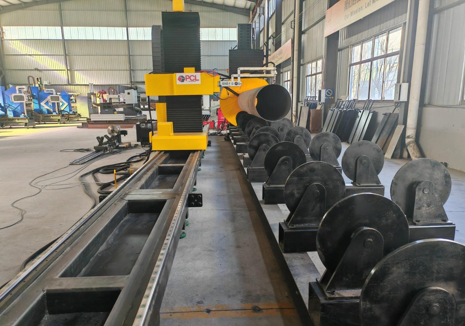
Achieving Precision in Intersection Accuracy
Large-scale construction equipment relies heavily on the intersection of tubular members and complex plate configurations. Intersection accuracy is the metric that determines how well two components fit together before the joining process. When processing heavy-duty boom sections or chassis frames, the plasma torch must execute precise trajectories that account for the curvature of the mating part.
High-definition plasma power sources play a vital role here. By utilizing oxygen-based plasma gases for carbon steel, the system produces a narrower, more focused arc. This results in a minimal heat-affected zone (HAZ) and a squareness that rivals mechanical machining. When the 5-axis head executes an intersection cut, it manages the “taper” effect inherent in plasma arcs by counter-tilting the torch. This ensures that the verticality of the cut remains within tight tolerances, typically +/- 0.5mm, which is more than sufficient for the rigorous standards of the heavy machinery industry.
Operational Efficiency in H-Beam Processing
Structural integrity in construction machinery often stems from the use of H-beams and I-beams in the primary frame. Traditional methods for processing these sections—such as sawing or drilling—are time-consuming and labor-intensive. A plasma system designed for beam processing utilizes a 5-axis robotic arm or a specialized gantry to reach all surfaces of the beam, including the flanges and the web, in a single setup.
The primary advantage here is the reduction in material handling. By integrating the cutting, beveling, and hole-piercing functions into one automated cycle, the production line eliminates the bottlenecks associated with moving massive steel sections between different workstations. Furthermore, the software-driven nature of plasma cutting allows for nesting complex parts within the beam profile, significantly improving material utilization rates.
Low Maintenance Requirements for High-Uptime Environments
In a high-volume manufacturing plant, machine downtime is the single greatest threat to profitability. Plasma cutting systems have evolved to offer a “low maintenance” profile, particularly compared to mechanical cutting tools that suffer from blade wear and breakage. The consumables in a plasma torch—the nozzle, electrode, and shield—are designed for quick replacement, often taking less than two minutes to swap out.
Modern plasma cutting machine designs incorporate self-diagnostic tools and automated gas consoles that monitor pressure and flow rates in real-time. This prevents the “catastrophic failure” of the torch head by alerting operators to consumable wear before the cut quality degrades. Additionally, the lack of high-speed moving parts (unlike mechanical saws) reduces the vibration-induced wear on the machine’s gantry and rail system, leading to a longer service life and more predictable maintenance intervals. For H-beam lines, this means the system can run multiple shifts with only scheduled, minor interventions.
Nesting Software and CAD/CAM Integration
The physical capabilities of the 5-axis head are only as effective as the software driving it. In the context of industrial engineering, the integration of 3D CAD models directly into the nesting software is paramount. The software must calculate the “unfolded” geometry of beveled parts and generate a toolpath that avoids collisions between the tilted torch and the workpiece or the support slats.
By using advanced nesting algorithms, manufacturers can minimize the “skeleton” waste. In the heavy machinery sector, where raw material costs represent a significant portion of the total product cost, even a 3% increase in nesting efficiency can result in substantial annual savings. Furthermore, the software can automatically apply lead-ins and lead-outs that prevent gouging at the start and end of the cut, ensuring that the intersection points of the bevel are clean and ready for the next stage of production.
Conclusion: The Strategic Impact on Throughput
For the industrial engineer tasked with optimizing a construction machinery assembly line, the 5-axis plasma cutting system offers a multi-faceted solution. It addresses the need for high-speed production without sacrificing the geometric precision required for heavy structural components. By mastering beveling and intersection accuracy, the facility can move parts directly from the cutting table to the assembly jig, bypassing the costly and inefficient grinding stations that once defined heavy fabrication.
Ultimately, the reliability of plasma technology—evidenced by its low maintenance demands and robust performance in dusty, high-heat environments—makes it the preferred choice for the rugged demands of the construction industry. As machinery designs become more complex and material specifications more stringent, the flexibility of 5-axis thermal cutting will continue to be a decisive factor in manufacturing competitiveness.
-


LT240S tube laser cutting machine
-
LT120S tube laser cutting machine
-
Sale

Tank Fillet Welding Machine
Original price was: $1,000.00.$900.00Current price is: $900.00. -
Sale

MAK100 tube laser cutting machine
Original price was: $5,500.00.$5,000.00Current price is: $5,000.00. -

portable plasma air cutting machine
$1,200.00 -

2in1 fiber laser cutting machine
-

Air cooling Laser welding machine
-

HF h beam laser cutting machine
-

LT240 laser cutting machine
-

Laser welding machine
-


Cobot Welding Station
-

Gantry welding robot solution
-

Tracked Wheeled AGV Welding robot
-

LFH6020 Fiber laser cutting machine
-
LFP6020
-

robotic welidng machine
Advanced Fiber Laser Tube Processing Technology
Our CNC Fiber Laser Tube Cutting systems revolutionize metal fabrication by integrating high-precision cutting, punching, and profiling into a single automated workflow. Designed for versatility, this technology handles a wide array of profiles including Round, Square, Rectangular, and Oval tubes, as well as complex L-shaped and U-shaped channels.
- Precision Punching: High-speed hole punching with micron-level accuracy, eliminating the need for mechanical drilling or die-stamping.
- Complex Profiling: Advanced 3D pathing allows for intricate interlocking joints and specialized notch cuts, ideal for structural frames.
- High Material Efficiency: Intelligent nesting software minimizes scrap, reducing raw material costs across large production runs.
- Clean Finish: Delivers oxide-free, burr-free edges that require zero secondary grinding before welding.

Seamlessly processing multiple profiles with consistent precision.
Global Delivery & Logistics



From our high-tech manufacturing facility directly to your global site. PCL WeldCut ensures secure packaging, professional handling, and reliable international logistics to safeguard your equipment throughout the entire journey.