Optimization of Shipbuilding Fabrication via Advanced Plasma Cutting
In the industrial engineering landscape of maritime construction, throughput and precision are the primary drivers of profitability. Shipbuilding requires the processing of massive structural components where dimensional deviations lead to exponential increases in assembly costs. The implementation of a Plasma Cutting Machine equipped with Laser Seam Tracking addresses the inherent challenges of thermal distortion and material irregularities found in large-scale steel plates and profiles. Unlike standard CNC cutting, these specialized systems focus on maintaining tight tolerances across long spans, ensuring that every component meets the stringent classification society standards.
The focus remains on the kinetic efficiency of the plasma arc. By utilizing high-definition oxygen or nitrogen-shielded plasma, engineers can achieve a narrow kerf and a reduced heat-affected zone (HAZ). This is critical for Shipbuilding steels, where maintaining the metallurgical integrity of the edge is vital for subsequent structural integrity.
The Role of Laser Seam Tracking in Intersection Accuracy
One of the most complex tasks in shipyard fabrication is the cutting of pipe-to-pipe or pipe-to-plate intersections. These geometries require non-linear tool paths where the torch angle must constantly change to account for the curvature of the workpiece. Intersection accuracy is often compromised by the physical reality of the material—plates are rarely perfectly flat, and large-diameter pipes often possess slight ovality.
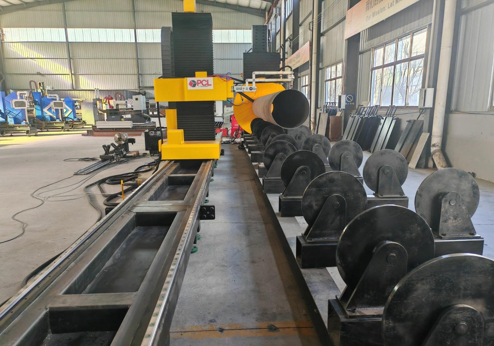
Laser seam tracking serves as a real-time sensory feedback loop. As the plasma torch moves along the programmed path, the laser sensor scans the material surface millimeters ahead of the arc. It detects the exact height and lateral position of the workpiece, feeding this data back to the CNC controller. The system then makes micro-adjustments to the torch height and offset. This ensures that the intersection profile is cut exactly as modeled in the CAD/CAM environment, regardless of material deformation. This level of precision is fundamental for ensuring that structural “T-joints” and “K-joints” fit perfectly during the hull assembly phase.
H-Beam Processing and Low Maintenance Requirements
Structural steel sections, specifically H-beams and I-beams, form the backbone of a vessel’s internal framework. Traditional methods of processing these beams—such as mechanical drilling or sawing—involve high consumable costs and frequent downtime for tool sharpening and replacement. Transitioning to 3D plasma cutting for beam fabrication introduces a low maintenance profile that is highly attractive to shipyard operations managers.
A plasma system designed for H-beams utilizes a multi-axis robotic arm or a specialized gantry to reach all faces of the beam. Because plasma is a non-contact cutting process, there is no mechanical stress exerted on the machine structure, which drastically reduces the wear on bearings, drive motors, and rails. The maintenance schedule is primarily limited to the replacement of nozzles and electrodes, which can be performed in minutes. Furthermore, the ability to cut bolt holes, copes, and notches in a single pass eliminates the need for multiple machines, reducing the floor space required and the complexity of the material handling system.
Advanced Beveling for Weld Preparation
In heavy industry, the quality of a weld is largely dependent on the quality of the edge preparation. Shipbuilding involves thick plates that necessitate complex beveling profiles, including V, Y, X, and K-cuts. Manual grinding of these bevels is labor-intensive and prone to human error, often resulting in inconsistent root gaps that lead to weld defects.
Modern plasma cutting machines incorporate high-degree-of-freedom bevel heads capable of tilting up to 45 or 50 degrees. When combined with laser tracking, the machine can maintain a consistent bevel angle even if the plate is warped. This is achieved through real-time compensation of the torch’s standoff distance. For the industrial engineer, this means the “as-cut” part is ready for the assembly floor with zero secondary processing. The accuracy of the bevel ensures that automated welding systems can later operate with predictable parameters, further streamlining the production pipeline.
Integrating CAD/CAM Data with Plasma Hardware
The efficiency of a plasma cutting system is also measured by its software integration. In shipbuilding, where thousands of unique parts are nested on a single ship, the transition from the 3D model to the cutting bed must be seamless. The software must calculate the specific kerf compensation required for different material thicknesses and gas pressures.
When the laser seam tracking data is integrated into this workflow, the system creates a “digital twin” of the actual material conditions. This allows for the dynamic adjustment of cutting speeds at corners and intersections to prevent over-burning or dross accumulation. The result is a clean, dross-free cut that adheres to the strictest tolerances of the marine industry. By focusing on these technical parameters, shipyards can achieve a higher “First Time Right” ratio, which is the ultimate metric for engineering efficiency.
Durability and Duty Cycle in Shipyard Environments
Shipyards are harsh environments characterized by dust, humidity, and temperature fluctuations. A plasma machine designed for this sector must feature a high duty cycle, often 100% at maximum output, to sustain multi-shift operations. The ruggedization of the laser tracking optics is equally important; these sensors are typically housed in pressurized, cooled enclosures to prevent the ingress of metallic dust and smoke.
From a lifecycle cost perspective, the combination of plasma technology and automated seam tracking offers a superior ROI. The reduction in scrap material alone, caused by precise nesting and accurate intersection cutting, often justifies the capital expenditure within the first year of operation. For the industrial engineer, the goal is clear: maximize the arc-on time and minimize the manual intervention between the raw plate and the finished structural component.
Conclusion on Technical Synergy
The synergy between high-definition plasma cutting and laser sensing technology represents the pinnacle of modern structural steel fabrication. By focusing on the specific needs of the maritime sector—namely intersection accuracy, efficient H-beam processing, and precise beveling—manufacturers can overcome the traditional bottlenecks of ship construction. The shift toward these automated, low-maintenance systems is not merely a technological upgrade but a strategic necessity for shipyards aiming to compete in a global market that demands shorter lead times and higher structural standards.
-


LT240S tube laser cutting machine
-
LT120S tube laser cutting machine
-
Sale

Tank Fillet Welding Machine
Original price was: $1,000.00.$900.00Current price is: $900.00. -
Sale

MAK100 tube laser cutting machine
Original price was: $5,500.00.$5,000.00Current price is: $5,000.00. -

portable plasma air cutting machine
$1,200.00 -

2in1 fiber laser cutting machine
-

Air cooling Laser welding machine
-

HF h beam laser cutting machine
-

LT240 laser cutting machine
-

Laser welding machine
-


Cobot Welding Station
-

Gantry welding robot solution
-

Tracked Wheeled AGV Welding robot
-

LFH6020 Fiber laser cutting machine
-
LFP6020
-

robotic welidng machine
Advanced Fiber Laser Tube Processing Technology
Our CNC Fiber Laser Tube Cutting systems revolutionize metal fabrication by integrating high-precision cutting, punching, and profiling into a single automated workflow. Designed for versatility, this technology handles a wide array of profiles including Round, Square, Rectangular, and Oval tubes, as well as complex L-shaped and U-shaped channels.
- Precision Punching: High-speed hole punching with micron-level accuracy, eliminating the need for mechanical drilling or die-stamping.
- Complex Profiling: Advanced 3D pathing allows for intricate interlocking joints and specialized notch cuts, ideal for structural frames.
- High Material Efficiency: Intelligent nesting software minimizes scrap, reducing raw material costs across large production runs.
- Clean Finish: Delivers oxide-free, burr-free edges that require zero secondary grinding before welding.

Seamlessly processing multiple profiles with consistent precision.
Global Delivery & Logistics



From our high-tech manufacturing facility directly to your global site. PCL WeldCut ensures secure packaging, professional handling, and reliable international logistics to safeguard your equipment throughout the entire journey.