Advanced Plasma Cutting Dynamics in Shipbuilding H-Beam Fabrication
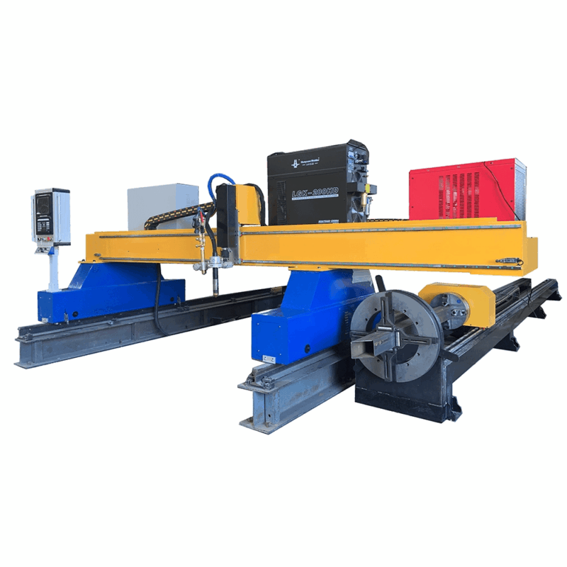
In the heavy industry sector of shipbuilding, the structural integrity of H-beams determines the vessel’s longitudinal strength and resistance to torsional stress. The production line must operate with mechanical precision to ensure that these structural components meet international maritime standards. A critical phase in this production involves the preparation of raw plates through High-Definition Plasma Cutting. Unlike lighter industrial applications, shipbuilding requires the processing of thick-grade carbon steel and high-tensile alloys where thermal management and edge quality are paramount. The plasma process provides the necessary energy density to penetrate thick sections while maintaining a controlled Heat Affected Zone (HAZ), ensuring that the metallurgical properties of the H-beam remain uncompromised before it enters the welding stage.
Precision Intersection Accuracy for Structural Fit-Up
The transition from individual plates to a unified H-beam requires impeccable intersection accuracy. In an automated H-Beam Production Line, the web and flange plates must meet with minimal deviation to facilitate the narrow gap welding process. Plasma cutting systems equipped with CNC-driven motion controllers allow for kerf compensation and real-time adjustments. When cutting the web plate, the verticality of the edge is essential; any angular deviation results in an uneven gap when the flanges are positioned.
High-definition plasma units utilize secondary gas shielding to constrict the arc, resulting in a narrower, more focused energy stream. This focus is vital for achieving Intersection Accuracy within tolerances of +/- 0.5mm over several meters. In the context of shipbuilding, where beams can exceed 15 meters in length, cumulative errors in cutting can lead to significant structural misalignment. By utilizing bridge-style plasma cutters with synchronized dual-side drives, the production line eliminates “snaking” effects, ensuring that the longitudinal edges of the web are perfectly parallel. This level of precision significantly reduces the need for secondary grinding or mechanical reworking, directly impacting the Overall Equipment Effectiveness (Effectiveness) of the fabrication facility.
Automated Beveling for Narrow Gap Welding Preparation
Narrow gap welding techniques demand specific groove geometries to ensure deep penetration with minimal filler metal consumption. Plasma cutting technology has evolved to include 5-axis and 6-axis robotic beveling heads that can perform V, Y, X, and K-cuts in a single pass. for Shipbuilding H-beams, Beveling Accuracy is the bottleneck of quality control. The plasma torch must maintain a consistent standoff distance through height sensing technologies, even when the plate exhibits slight surface irregularities or thermal warping.
The bevel angle must be maintained with extreme consistency because narrow gap welding relies on a tight, uniform groove. If the bevel angle fluctuates by even a few degrees, the welding arc may fail to fuse the side walls properly, leading to internal defects such as lack of fusion or slag inclusions. Advanced plasma systems integrate “True Bevel” technology, which automatically calculates the necessary offsets and gas pressures based on the desired angle and material thickness. This automation removes the margin for human error and ensures that the weld preparation is optimized for high-speed automated welding heads further down the production line.
Maximizing Uptime through Low Maintenance Systems
Industrial engineers prioritize Production Throughput, which is often hindered by frequent maintenance cycles. Modern plasma systems for H-beam lines are engineered for heavy duty-cycles (often 100% at maximum amperage). The focus on low maintenance is achieved through several key engineering features:
- Quick-change consumable cartridges that allow operators to swap electrodes and nozzles in seconds, reducing idle time.
- Advanced liquid cooling systems that circulate coolant directly to the torch tip, extending the lifespan of consumables even during prolonged cuts on 50mm plate.
- Robust dust and fume extraction systems that protect the mechanical rails and rack-and-pinion drives from abrasive metallic dust.
By reducing the frequency of intervention, the production line maintains a steady flow. In a shipyard environment, where downtime can cost thousands of dollars per hour, the reliability of the plasma power supply and its ability to withstand voltage fluctuations is a decisive factor in equipment selection. A low-maintenance plasma system ensures that the front end of the H-beam line never becomes a bottleneck for the subsequent assembly and welding stations.
Thermal Distortion Control and Material Utilization
One of the primary challenges in plasma cutting for large-scale H-beams is thermal distortion. As the plasma arc introduces intense heat into the plate, the material tends to expand and contract, which can bow the long strips required for flanges. Industrial-grade plasma lines mitigate this through optimized nesting software and “bridge cutting” techniques. By leaving small tabs of material or using water-table cutting surfaces, the heat is dissipated more effectively. This ensures that when the flange is welded to the web, the entire H-beam remains straight and true to the design specifications. Proper heat management during the cutting phase is a prerequisite for successful narrow gap welding, as any pre-existing stress in the plates will be exacerbated during the welding cycle.
Integration with Narrow Gap welding Requirements
The synergy between the plasma cutting station and the narrow gap welding station is the hallmark of a modern shipbuilding H-beam line. The plasma cutter is not merely a tool for separation but a precision instrument for edge preparation. By delivering a surface finish that meets ISO 9013 standards, the plasma system ensures that the welding arc remains stable. Surface roughness must be minimized to prevent gas turbulence during the welding process. Furthermore, the absence of dross (slag) on the bottom edge of the cut—achievable through high-speed plasma gas optimization—eliminates the need for manual cleaning, allowing the H-beam to move seamlessly from the cutting bed to the assembly jig. This integrated approach shortens lead times and enhances the structural reliability of the vessel’s framework.
-


LT240S tube laser cutting machine
-
LT120S tube laser cutting machine
-
Sale

Tank Fillet Welding Machine
Original price was: $1,000.00.$900.00Current price is: $900.00. -
Sale

MAK100 tube laser cutting machine
Original price was: $5,500.00.$5,000.00Current price is: $5,000.00. -

portable plasma air cutting machine
$1,200.00 -

2in1 fiber laser cutting machine
-

Air cooling Laser welding machine
-

HF h beam laser cutting machine
-

LT240 laser cutting machine
-

Laser welding machine
-


Cobot Welding Station
-

Gantry welding robot solution
-

Tracked Wheeled AGV Welding robot
-

LFH6020 Fiber laser cutting machine
-
LFP6020
-

robotic welidng machine
Advanced Fiber Laser Tube Processing Technology
Our CNC Fiber Laser Tube Cutting systems revolutionize metal fabrication by integrating high-precision cutting, punching, and profiling into a single automated workflow. Designed for versatility, this technology handles a wide array of profiles including Round, Square, Rectangular, and Oval tubes, as well as complex L-shaped and U-shaped channels.
- Precision Punching: High-speed hole punching with micron-level accuracy, eliminating the need for mechanical drilling or die-stamping.
- Complex Profiling: Advanced 3D pathing allows for intricate interlocking joints and specialized notch cuts, ideal for structural frames.
- High Material Efficiency: Intelligent nesting software minimizes scrap, reducing raw material costs across large production runs.
- Clean Finish: Delivers oxide-free, burr-free edges that require zero secondary grinding before welding.

Seamlessly processing multiple profiles with consistent precision.
Global Delivery & Logistics



From our high-tech manufacturing facility directly to your global site. PCL WeldCut ensures secure packaging, professional handling, and reliable international logistics to safeguard your equipment throughout the entire journey.