Technical Foundation of H-Beam Plasma Profiling
In the realm of structural steel fabrication, the H-Beam Production Line serves as the primary engine for converting raw mill sections into precision-engineered components. Unlike plate processing, H-beam fabrication involves multi-dimensional geometries where the web and flanges must be processed simultaneously or in a synchronized sequence. The shift toward automated Plasma Cutting has been driven by the need for higher throughput and superior edge quality without the thermal distortion common in older oxy-fuel methods.
The core efficiency of a modern H-beam line is predicated on its ability to handle structural variations. Mill-rolled H-beams are rarely perfectly straight or flat. They often possess slight flange warps or web deviations. To maintain consistent cutting quality, the integration of advanced motion control and sensing technology is mandatory. This is where plasma systems, optimized for the structural steel environment, provide a significant advantage over mechanical drilling or manual sawing.
The Critical Role of Arc Voltage Control (AVC)
Arc Voltage Control is the primary mechanism ensuring vertical precision during the plasma cutting process. In a high-definition plasma system, the voltage between the torch electrode and the workpiece is directly proportional to the distance between them. As the H-beam moves through the cutting zone, any deviation in the beam’s surface height is detected as a change in arc voltage.
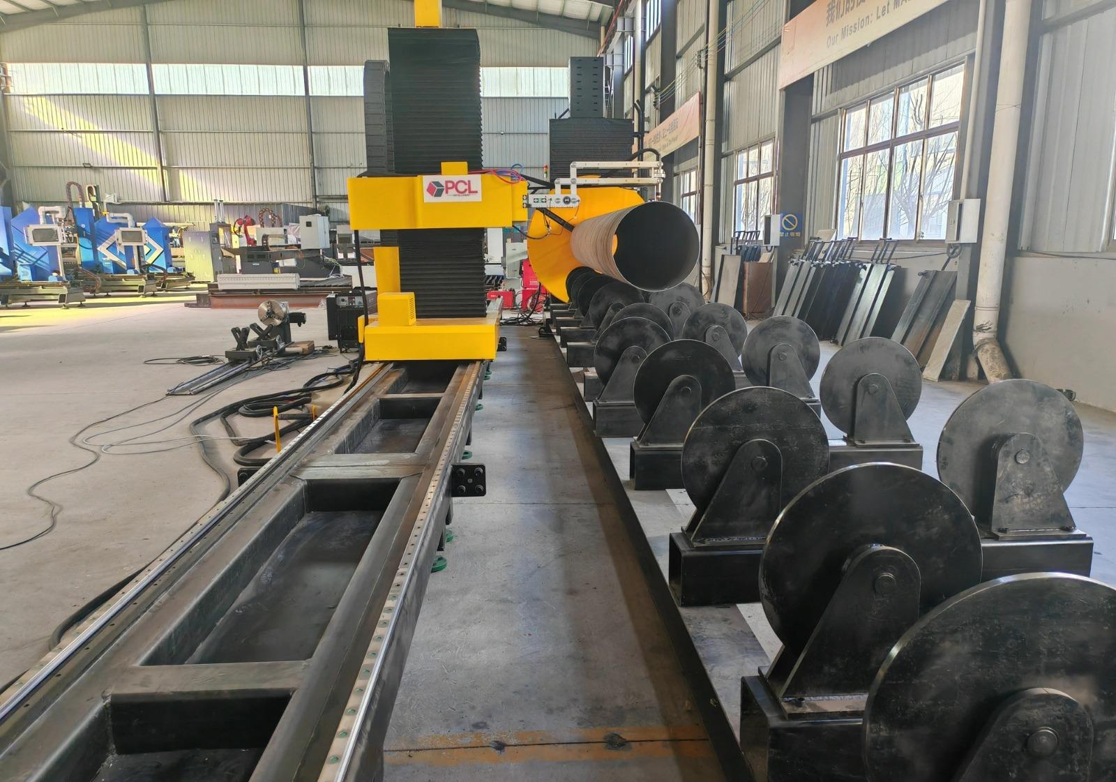
The AVC system functions as a high-speed closed-loop feedback mechanism. If the distance between the torch and the flange increases, the voltage rises; the controller detects this change and instantly signals the Z-axis servo motor to lower the torch. This constant adjustment ensures that the plasma arc remains at its optimal focal point, preventing “dross” or excessive slag accumulation. For H-beam production, where flange thicknesses vary and structural tension can cause the beam to shift slightly during the thermal process, AVC is the only reliable method to prevent torch collisions and ensure a uniform kerf width across the entire length of the cut.
Achieving Superior Intersection Accuracy
In steel structure assembly, the “fit-up” of intersecting beams determines the structural integrity and the speed of the final assembly. Intersection accuracy refers to the precision with which the plasma torch executes complex “coping” cuts—such as flange thins, web penetrations, and bolt holes.
A high-performance H-beam line utilizes multi-axis robotic arms or specialized Cartesian gantry systems that can rotate around the beam. By synchronizing the beam feed (X-axis) with the torch rotation (R-axis) and elevation (Z-axis), the system can cut complex geometric intersections with tolerances within +/- 0.5mm. This level of precision eliminates the need for manual “re-work” on the shop floor. When the secondary beam meets the primary girder, the contours match perfectly, allowing for immediate bolting or further processing without gaps or overlaps. This precision is particularly vital for seismic-resistant structures where tight tolerances are non-negotiable.
Advanced Beveling for Weld Preparation
One of the most significant bottlenecks in traditional H-beam fabrication is the manual preparation of weld bevels. Modern plasma-integrated lines address this through automated beveling efficiency. The plasma head is capable of tilting to execute V, Y, X, and K-style bevels directly on the web or flange edges during the initial cutting pass.
The use of Arc Voltage Control during beveling is more complex than straight cutting. As the torch tilts, the relative distance to the metal changes. Advanced software algorithms calculate the “voltage offset” required to maintain the arc length at an angle. This allows the H-beam line to produce ready-to-assemble components that require zero secondary grinding. By integrating the beveling process into the main cutting cycle, the production line reduces material handling time and labor costs, as the beam does not need to be moved to a separate station for edge preparation.
H-Beam Low Maintenance Design Logic
Industrial engineers prioritize “Up-time” above all else. Plasma-based H-beam lines are engineered for a low-maintenance lifecycle compared to mechanical processing centers. Mechanical systems rely on drill bits, milling cutters, and cooling fluids, all of which require frequent replacement and generate significant waste.
In contrast, a plasma system is a non-contact thermal process. The primary wear components are restricted to the torch consumables—nozzles, electrodes, and swirl rings. Modern H-beam lines feature “Quick-Change” torch bodies that allow operators to swap consumables in under two minutes. Furthermore, because plasma does not exert physical force on the H-beam, the structural frame of the machine experiences less vibration and mechanical fatigue. This translates to longer intervals between calibration and reduced wear on the linear guides and rack-and-pinion drive systems. The absence of cutting fluids also results in a cleaner work environment and eliminates the need for complex filtration and disposal systems.
Integrating Software with Hardware for Maximum Throughput
The hardware of an H-beam line is only as effective as the nesting and control software governing it. High-SEO industrial systems now utilize direct CAD-to-CAM pipelines. An engineer can export a TEKLA or DSTV file directly to the production line. The software analyzes the beam geometry, identifies all necessary intersections and bevels, and optimizes the cutting path to minimize “air-cut” time.
This digital integration ensures that the AVC parameters are pre-set based on the material thickness and gas mixture (typically Oxygen or Nitrogen-Shielded). The synchronization between the software and the physical plasma arc allows for “fly-cutting” capabilities, where the torch moves fluidly between features without unnecessary retracting, further boosting the parts-per-hour metric.
Conclusion on Structural Steel Optimization
The implementation of a plasma-based H-beam production line equipped with Arc Voltage Control represents a significant leap in structural engineering efficiency. By focusing on the physics of the arc and the precision of multi-axis motion, fabricators can achieve a level of intersection accuracy that was previously impossible at high speeds. The combination of automated beveling and the inherent low-maintenance nature of plasma technology creates a robust system capable of meeting the rigorous demands of modern steel construction. As structural designs become more complex, the reliance on these high-precision, automated cutting solutions will only continue to grow, ensuring that the backbone of our infrastructure is built with uncompromising accuracy and efficiency.
-


LT240S tube laser cutting machine
-
LT120S tube laser cutting machine
-
Sale

Tank Fillet Welding Machine
Original price was: $1,000.00.$900.00Current price is: $900.00. -
Sale

MAK100 tube laser cutting machine
Original price was: $5,500.00.$5,000.00Current price is: $5,000.00. -

portable plasma air cutting machine
$1,200.00 -

2in1 fiber laser cutting machine
-

Air cooling Laser welding machine
-

HF h beam laser cutting machine
-

LT240 laser cutting machine
-

Laser welding machine
-


Cobot Welding Station
-

Gantry welding robot solution
-

Tracked Wheeled AGV Welding robot
-

LFH6020 Fiber laser cutting machine
-
LFP6020
-

robotic welidng machine
Advanced Fiber Laser Tube Processing Technology
Our CNC Fiber Laser Tube Cutting systems revolutionize metal fabrication by integrating high-precision cutting, punching, and profiling into a single automated workflow. Designed for versatility, this technology handles a wide array of profiles including Round, Square, Rectangular, and Oval tubes, as well as complex L-shaped and U-shaped channels.
- Precision Punching: High-speed hole punching with micron-level accuracy, eliminating the need for mechanical drilling or die-stamping.
- Complex Profiling: Advanced 3D pathing allows for intricate interlocking joints and specialized notch cuts, ideal for structural frames.
- High Material Efficiency: Intelligent nesting software minimizes scrap, reducing raw material costs across large production runs.
- Clean Finish: Delivers oxide-free, burr-free edges that require zero secondary grinding before welding.

Seamlessly processing multiple profiles with consistent precision.
Global Delivery & Logistics



From our high-tech manufacturing facility directly to your global site. PCL WeldCut ensures secure packaging, professional handling, and reliable international logistics to safeguard your equipment throughout the entire journey.