Thermal Processing Standards for Heavy-Duty Structural H-Beams
In the manufacturing of construction machinery—such as crawler cranes, excavators, and drilling rigs—the structural integrity of the chassis and boom components is paramount. The H-Beam Production Line has transitioned from manual layout and mechanical sawing to sophisticated thermal processing units. The shift toward 5-axis plasma systems is driven by the need for multi-dimensional geometric freedom. Unlike traditional 2D cutting, a 5-axis system incorporates rotational and tilting axes (typically A and B axes), allowing the torch to maintain a perpendicular or specific angular orientation relative to the beam’s web and flanges simultaneously.
The engineering objective in these production lines is to eliminate secondary processing. By utilizing high-definition plasma power sources, manufacturers can achieve dross-free cuts on thick-walled H-beams, ensuring that the components are ready for assembly immediately after the thermal cycle. This efficiency is critical when handling high-strength low-alloy (HSLA) steels commonly found in the construction equipment sector.
Advanced Kinematics in 5-Axis Beveling
The core of the 5-axis plasma system lies in its ability to execute complex motion paths across the X, Y, Z, A, and B planes. In an H-beam context, the “5-axis” capability refers to the torch’s ability to tilt (bevel) while rotating around the vertical axis, all while traversing the longitudinal and transverse dimensions of the beam. This is essential for creating “cope” cuts or “rat holes” that are dimensionally accurate across both the web and the flanges.
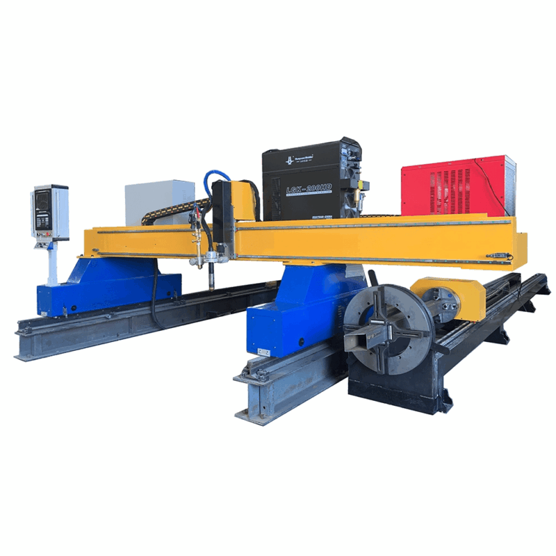
From a mechanical engineering perspective, the 5-axis Plasma Cutting head must be coupled with a robust CNC controller capable of real-time coordinate transformation. When cutting a bevel on the flange of an H-beam, the software must account for the beam’s structural tolerances, such as flange tilt or web eccentricity. Advanced systems utilize laser or mechanical touch-probing to map the actual profile of the beam before the arc is struck, ensuring the bevel angle remains constant despite any mill-induced deformations in the raw material.
Achieving Superior Intersection Accuracy
One of the most significant challenges in construction machinery fabrication is the precision of intersecting members. Whether it is a cross-brace for a crane boom or a mounting bracket for a hydraulic cylinder, the intersection accuracy determines the load-bearing capacity of the final structure. Plasma cutting provides a unique advantage here through kerf compensation algorithms.
In a 5-axis environment, the intersection of two H-beams requires a non-linear cut path that accounts for the thickness of the material and the angle of the join. The plasma arc, though a thermal tool, can be tightly controlled to mimic the precision of mechanical milling. By modulating the gas flow (O2 for carbon steel) and the arc voltage, the system maintains a consistent “sweet spot” in the plasma flame. This results in an intersection where the gap between members is minimized to sub-millimeter tolerances, providing a perfect fit-up for subsequent assembly stages.
Optimizing Maintenance via Plasma Technology
A primary KPI for industrial engineers is the Mean Time Between Failures (MTBF) and the overall cost of consumables. Traditional mechanical methods—such as drilling, milling, or sawing—involve significant tool wear and require frequent sharpening or replacement of carbide tips. Conversely, a low maintenance plasma system relies on high-velocity gas and electrical ionization.
The primary wear items in a plasma torch are the nozzle, electrode, and swirl ring. Modern high-definition systems feature “long-life” technology that sequences the cooling of the electrode to prevent hafnium blowout. Because there is no physical contact between the cutting tool and the workpiece, there is no mechanical stress on the gantry or the drive motors. This lack of vibration extends the lifespan of the linear guides and rack-and-pinion systems, drastically reducing the maintenance overhead compared to mechanical beam-drilling lines. Furthermore, the absence of cutting fluids or coolants simplifies the workspace and reduces environmental disposal costs.
Beveling Profiles for Structural Integrity
Construction machinery requires various bevel types to facilitate deep penetration in thick plate sections. The 5-axis plasma head is capable of producing several standardized profiles in a single pass:
- V-Bevel: A standard angular cut on the edge of the flange or web.
- Y-Bevel: A combination of a vertical land and an angular bevel, crucial for maintaining root opening consistency.
- K and X Bevels: Double-sided bevels used for maximum thickness sections where structural loads are bidirectional.
The ability to program these bevels directly into the CNC nesting software allows for the automated production of “ready-to-assemble” parts. The 5-axis head adjusts its tilt angle dynamically as it moves around the flange corners, a process known as “corner looping,” which ensures that the bevel geometry does not distort during directional changes.
Data Integration and Nesting Efficiency
For an H-beam production line to be truly efficient, the 5-axis plasma system must be integrated with CAD/CAM software tailored for structural steel. This software takes 3D models (often in STEP or IGES format) and flattens them into machine-readable G-code. The nesting process is not just about material utilization; it is about “common cut” optimization and lead-in/lead-out placement to prevent heat-affected zone (HAZ) complications at critical stress points.
In construction machinery, where beam sections are often oversized, the software must also manage “multiturn” processing. This involves rotating the beam 90 or 180 degrees to reach all four sides. A 5-axis plasma system equipped with an automated beam rotator ensures that the coordinate system is re-aligned perfectly after each rotation, maintaining the intersection accuracy across all faces of the beam. This level of automation reduces the reliance on overhead cranes and manual flipping, further enhancing the safety and throughput of the facility.
Conclusion: The Industrial Engineering Advantage
The deployment of 5-axis plasma cutting in an H-beam production line represents a strategic investment in precision and operational longevity. By prioritizing high-definition thermal cutting over mechanical alternatives, manufacturers of construction machinery can achieve the complex geometries required for modern heavy equipment while minimizing the maintenance footprint. The synergy between 5-axis kinematics and advanced plasma power sources ensures that every H-beam produced meets the rigorous safety and performance standards of the global construction industry.
-


LT240S tube laser cutting machine
-
LT120S tube laser cutting machine
-
Sale

Tank Fillet Welding Machine
Original price was: $1,000.00.$900.00Current price is: $900.00. -
Sale

MAK100 tube laser cutting machine
Original price was: $5,500.00.$5,000.00Current price is: $5,000.00. -

portable plasma air cutting machine
$1,200.00 -

2in1 fiber laser cutting machine
-

Air cooling Laser welding machine
-

HF h beam laser cutting machine
-

LT240 laser cutting machine
-

Laser welding machine
-


Cobot Welding Station
-

Gantry welding robot solution
-

Tracked Wheeled AGV Welding robot
-

LFH6020 Fiber laser cutting machine
-
LFP6020
-

robotic welidng machine
Advanced Fiber Laser Tube Processing Technology
Our CNC Fiber Laser Tube Cutting systems revolutionize metal fabrication by integrating high-precision cutting, punching, and profiling into a single automated workflow. Designed for versatility, this technology handles a wide array of profiles including Round, Square, Rectangular, and Oval tubes, as well as complex L-shaped and U-shaped channels.
- Precision Punching: High-speed hole punching with micron-level accuracy, eliminating the need for mechanical drilling or die-stamping.
- Complex Profiling: Advanced 3D pathing allows for intricate interlocking joints and specialized notch cuts, ideal for structural frames.
- High Material Efficiency: Intelligent nesting software minimizes scrap, reducing raw material costs across large production runs.
- Clean Finish: Delivers oxide-free, burr-free edges that require zero secondary grinding before welding.

Seamlessly processing multiple profiles with consistent precision.
Global Delivery & Logistics



From our high-tech manufacturing facility directly to your global site. PCL WeldCut ensures secure packaging, professional handling, and reliable international logistics to safeguard your equipment throughout the entire journey.