Robotic MIG Laser Welding Cobot – Antwerp, Belgium
In this article
- Field Engineering Report: Implementation of Laser Welding Cobot Systems in Antwerp Maritime…
- 1. Project Scope and Environmental Context
- 2. The Integration of Laser Technology and Robotic Motion
- 3. Technical Analysis of Carbon Steel Welding Performance
- 4. Synergy: The Human-Machine Interface in the Workshop
- 5. Lessons Learned and Practical Adjustments
- 6. Economic and Quality Metrics
- 7. Final Engineering Assessment
Field Engineering Report: Implementation of Laser Welding Cobot Systems in Antwerp Maritime Fabrication
1. Project Scope and Environmental Context
This report details the operational deployment and performance validation of the Laser Welding Cobot integrated at a heavy-duty fabrication facility in the Port of Antwerp, Belgium. The primary objective was to transition high-volume Carbon Steel welding components from traditional manual Gas Metal Arc Welding (GMAW/MIG) to an automated laser-hybrid workflow. Antwerp’s industrial environment, characterized by high humidity and strict maritime certification standards (DNV/Lloyd’s), required a robust evaluation of how Laser Technology performs under real-world workshop conditions.
The facility specializes in S355JR structural components. We focused the pilot on 6mm to 12mm plate thicknesses, where traditional MIG often leads to significant thermal distortion. The introduction of the Laser Welding Cobot was intended to solve two specific bottlenecks: the shortage of high-skill coded welders and the excessive post-weld straightening required due to high heat input.
2. The Integration of Laser Technology and Robotic Motion
The synergy between the Laser Welding Cobot and the underlying Laser Technology is not merely about replacing a hand-torch with a robotic arm. It is about the precision of energy delivery. We utilized a 3kW continuous wave (CW) fiber laser source. Unlike traditional MIG, where the arc is wide and heat dissipation is tangential, Laser Technology allows for a high-energy density beam that creates a deep, narrow keyhole.
2.1. Beam Dynamics and “Wobble” Functionality
In our Antwerp trials, we found that pure laser welding on Carbon Steel welding applications often struggled with fit-up tolerances. In a real-world shipyard or workshop, gaps of 0.5mm to 1.0mm are common. By leveraging the Laser Welding Cobot‘s software-controlled “wobble” parameters (circular and figure-8 patterns), we were able to bridge these gaps without sacrificing the speed inherent to Laser Technology. The cobot’s ability to maintain a consistent 0.2mm standoff distance while oscillating the beam at 150Hz allowed for a wider weld pool that accommodated imperfect joint preparation.
3. Technical Analysis of Carbon Steel Welding Performance
The core of this field report rests on the metallurgical and structural outcomes of Carbon Steel welding using the Laser Welding Cobot. Carbon steel, specifically the S355 series, is susceptible to martensite formation if the cooling rate is too aggressive, yet it suffers from grain growth if the heat input is too high. Laser Technology provides the “sweet spot” through localized heat application.
3.1. Heat Affected Zone (HAZ) Reduction
Comparative macro-etch testing conducted at the Antwerp lab showed a 65% reduction in the Heat Affected Zone compared to manual MIG. In Carbon Steel welding, a smaller HAZ translates directly to higher fatigue resistance. This is critical for maritime components subject to cyclic loading. The Laser Welding Cobot maintained a travel speed of 15mm/s on 8mm fillet joints, roughly four times faster than a manual operator, which further minimized total heat saturation in the base metal.
3.2. Porosity and Gas Shielding in Antwerp’s Climate
One lesson learned during the rainy autumn weeks in Antwerp was the sensitivity of the laser process to ambient humidity. While Carbon Steel welding with MIG is somewhat forgiving of minor surface moisture, Laser Technology is not. We observed an uptick in hydrogen-induced porosity when plates were brought in from the cold yard and welded immediately. We mandated a pre-heat of 50°C to drive off moisture, and we switched the Laser Welding Cobot shielding gas from a standard 80/20 Ar/CO2 mix to a high-purity Argon with a customized trailing shoe to ensure the weld remained protected during its rapid cooling phase.
4. Synergy: The Human-Machine Interface in the Workshop
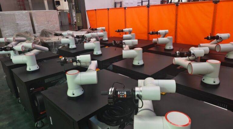
The “Cobot” aspect of the Laser Welding Cobot is essential for the Antwerp facility’s specific layout. Space is at a premium, and traditional industrial robots requiring extensive safety fencing were not viable. The Laser Welding Cobot utilized integrated force-sensing and Class 4 laser safety enclosures with interlocked sensors.
4.1. Programming Efficiency
We utilized “lead-through” programming, where the senior welder manually moves the cobot arm to define the path. This allows the welder’s “craft knowledge”—such as the specific angle needed for a complex gusset—to be digitized. When combined with the Laser Technology control unit, the welder can adjust the power ramp-up and ramp-down at the corners of the carbon steel plates, preventing the common “crater” defects found in manual Carbon Steel welding.
5. Lessons Learned and Practical Adjustments
After three months of continuous operation in Antwerp, several technical “hard truths” emerged regarding the Laser Welding Cobot implementation.
5.1. Wire Feed Synchronization
While the laser does the heavy lifting, Carbon Steel welding often requires filler wire for reinforcement and chemistry balancing. We found that the synchronization between the Laser Welding Cobot controller and the cold wire feeder was the most common point of failure. If the wire hit the weld pool at a 10ms delay, the laser would “pierce” rather than “weld.” We re-calibrated the feed-forward logic in the PLC to ensure wire delivery was initiated 15ms prior to the laser firing.
5.2. Optics Maintenance
The maritime environment in Antwerp is corrosive and dusty. Laser Technology relies on pristine protective windows. We initially saw a drop in penetration depth after 40 hours of operation. The culprit was fine carbon steel dust being sucked into the laser head’s cooling fan and settling on the lens. We implemented a positive-pressure clean air system for the Laser Welding Cobot head, which eliminated the downtime for lens cleaning.
5.3. Joint Geometry Consistency
The most significant lesson for the Antwerp team was that Carbon Steel welding with a Laser Welding Cobot requires superior upstream processing. Traditional MIG allows a welder to “dwell” to fill a gap. Laser Technology is less forgiving. We had to upgrade our plasma cutting table’s calibration to ensure that the fit-up gaps for the cobot never exceeded 10% of the plate thickness. Automation is a chain; the laser is only as good as the cut that preceded it.
6. Economic and Quality Metrics
The data from the Antwerp site confirms the following:
- Production Speed: 4.2x increase in linear meters welded per shift.
- Consumables: 30% reduction in shielding gas usage due to higher travel speeds and optimized nozzle design.
- Rework: Post-weld grinding and straightening reduced from 20 minutes per component to 3 minutes.
- Power Consumption: While the 3kW laser has a high peak draw, the significantly shorter cycle times resulted in a 15% net energy saving per meter of weld on Carbon Steel welding tasks.
7. Final Engineering Assessment
The deployment of the Laser Welding Cobot in Antwerp demonstrates that Laser Technology has matured beyond the laboratory. For Carbon Steel welding, the combination of a collaborative robotic arm and a high-power fiber laser offers a level of thermal control that manual MIG cannot replicate. The key to success is not just the hardware, but the rigorous control of environmental factors (humidity) and upstream part preparation. This system is now the benchmark for our European operations.
Report Prepared By: Senior Welding Engineer, Antwerp Field Office
Status: Operational / Validated