Field Engineering Report: Implementation of 6-Axis Collaborative Welder for Carbon Steel in Queretaro, Mexico
1. Introduction and Project Scope
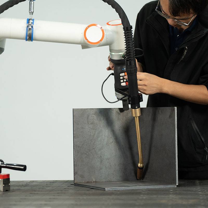
This report details the technical commissioning and performance evaluation of the low-spatter MAG (Metal Active Gas) system integrated with a 6-axis collaborative welder at a Tier 1 automotive structural plant in Queretaro, Mexico. The facility primarily handles high-volume carbon steel welding for chassis reinforcements. The primary objective was to transition a manual welding station—previously plagued by inconsistent bead quality and excessive post-weld cleanup—into a high-efficiency Automated Welding cell.
Queretaro’s industrial environment presents specific challenges, including significant ambient temperature fluctuations and the need for rapid deployment to meet tight supply chain windows. The implementation of a 6-axis collaborative welder was selected over traditional industrial robotics due to floor space constraints and the requirement for “man-side-by-side” operation without extensive safety fencing.
2. The Synergy of 6-Axis Collaborative Welder and Automated Welding
In the context of the Queretaro facility, the term “automated welding” has evolved. We are no longer discussing fixed automation that requires weeks of PLC (Programmable Logic Controller) programming. The synergy here lies in the 6-axis collaborative welder’s ability to mimic human dexterity while maintaining the precision of a computer-controlled system.
2.1 Kinematic Flexibility
The 6-axis configuration is critical for carbon steel welding when dealing with complex geometries like gussets and curved tubular frames. Each axis allows the torch to maintain the optimal work angle and travel angle, specifically the 15-degree push technique required for MAG welding to ensure gas coverage. Unlike 4-axis systems, the 6-axis collaborative welder can navigate around clamps and fixtures that would otherwise cause “singularities” or mechanical interference in a less flexible arm.
2.2 Integration of the “Collaborative” Element
Automated welding in this plant is now a hybrid process. The “collaborative” aspect allows the lead welder to “teach” the robot by physically moving the arm to the start and end points of a weld. This reduces programming time from hours to minutes. In the Queretaro workshop, this allowed us to shift from a batch of 100 parts to a different part number in under fifteen minutes, a feat impossible with legacy automated welding cells.
3. Technical Specifications for Carbon Steel Welding
Carbon steel welding remains the backbone of the Queretaro industrial sector. For this project, we utilized AWS A5.18 ER70S-6 solid wire (1.2mm diameter) with a 90% Argon / 10% CO2 shielding gas mix. The focus was on achieving a “low-spatter” result to eliminate the secondary grinding operation.
3.1 Waveform Control and Spatter Reduction
The low-spatter MAG process is achieved through high-speed inverter technology that monitors the short-circuit cycle. By reducing the current immediately before the molten droplet detaches from the wire (the “pinch” effect), we effectively neutralized the “explosion” that creates spatter. In our field tests, spatter accumulation on the workpiece was reduced by 85% compared to the previous manual GMAW (Gas Metal Arc Welding) setup.
3.2 Heat Input Management
A recurring issue in Queretaro’s carbon steel welding applications is thermal distortion in thin-gauge (3mm to 5mm) plates. The 6-axis collaborative welder provides a constant travel speed—exactly 380mm/min in our optimized program—which ensures uniform heat input. This consistency prevented the “oil-canning” effect observed in manually welded parts, where heat saturation varies based on operator fatigue.
4. Field Observations: Queretaro Site Specifics
The Queretaro region is known for its high-altitude (approx. 1,800m) and varying humidity levels. During the commissioning phase, we noted that the shielding gas flow needed adjustment compared to our sea-level baseline. We increased the flow rate to 18-20 L/min to compensate for the thinner air and ensure the arc remained stable.
4.1 Power Grid Stability
One “lesson learned” during the first week was the impact of local grid fluctuations on the 6-axis collaborative welder’s sensitivity. We observed minor positioning errors during peak industrial hours (2 PM – 4 PM). The solution was the installation of a dedicated power conditioner and a regulated 24V DC supply for the cobot controller to ensure that the automated welding path remained repeatable within +/- 0.1mm.
5. Lessons Learned and Engineering Adjustments
No deployment is without friction. Here are the three primary engineering adjustments made during the Queretaro implementation:
5.1 Tool Center Point (TCP) Calibration
Initially, we experienced “arc wander.” We discovered that the automated welding torch was slightly deforming due to heat soak during 80% duty cycle runs. We implemented a “TCP Check” routine every 50 cycles, where the 6-axis collaborative welder moves to a fixed reference pin. If the deviation exceeds 0.5mm, the system alerts the operator. This is a critical protocol for carbon steel welding where fillet leg length must be precise for structural integrity.
5.2 Wire Feed Consistency
In automated welding, the wire delivery system is the most common point of failure. We moved from standard 15kg spools to 250kg “marathon packs.” The 6-axis arm moves constantly, and we found that the standard conduit was creating excessive friction (drag) at certain arm orientations. We switched to a high-flex, low-friction ceramic-lined liner, which stabilized the motor current on the wire feeder and further reduced spatter.
5.3 Fixturing and Tolerances
A 6-axis collaborative welder is only as good as the part presentation. We found that the manual jigs used previously had +/- 2.0mm of play. While a human welder compensates for this gap instinctively, the automated welding system does not (unless using expensive seam-tracking sensors). We had to re-engineer the pneumatic clamps to hold the carbon steel components to a tolerance of +/- 0.5mm. This reinforces the rule: Automation requires disciplined upstream fabrication.
6. Productivity and ROI Analysis
Before the introduction of the 6-axis collaborative welder, the station produced 12 finished frames per hour, including the time required for spatter removal and manual inspection. Post-implementation, the output increased to 22 frames per hour.
The “low-spatter” MAG technology was the primary driver of this 83% increase in throughput. By eliminating the need for a dedicated “grinding station” downstream, we freed up two technicians to move into more skilled roles, such as cobot programming and quality assurance. In the Queretaro market, where skilled welding labor is increasingly expensive and scarce, this efficiency is the only viable path forward for carbon steel welding operations.
7. Conclusion
The deployment in Queretaro confirms that the integration of a 6-axis collaborative welder into an automated welding workflow is no longer a luxury—it is a technical necessity for high-volume carbon steel welding. The low-spatter MAG process, when combined with the kinematic flexibility of a 6-axis arm, solves the dual problems of quality and throughput.
For future deployments, we recommend a “fixture-first” approach, ensuring that part repeatability matches the precision of the robotic arm. Furthermore, the Queretaro facility will now serve as a blueprint for our other Mexican operations, proving that “collaborative” does not mean “slow”—it means “smart” and “scalable.”
End of Report
Prepared by: Senior Welding Engineer, Automation Division
Location: Queretaro, Mexico
Status: Commissioning Complete / Production Live
-

Cantilever Welding Robot solution
-

GF laser cutting machine
-

P3015 plasma cutting machine
-

LFP3015 Fiber Laser Cutter
-

pipe plasma cutting machine
-
LFH 4020 Fiber Laser Cutting Machine
-
LFP4020
-

gantry plasma air cutting machine
-

3D robot cutting machine
-

8 axis plasma cutting machine
-

5 axis plasma cutting machine
-

LT360 tube laser cutting machine
-

robot welding workstation
-

SF6060 fiber laser cutting machine
Advanced Fiber Laser Tube Processing Technology
Our CNC Fiber Laser Tube Cutting systems revolutionize metal fabrication by integrating high-precision cutting, punching, and profiling into a single automated workflow. Designed for versatility, this technology handles a wide array of profiles including Round, Square, Rectangular, and Oval tubes, as well as complex L-shaped and U-shaped channels.
- Precision Punching: High-speed hole punching with micron-level accuracy, eliminating the need for mechanical drilling or die-stamping.
- Complex Profiling: Advanced 3D pathing allows for intricate interlocking joints and specialized notch cuts, ideal for structural frames.
- High Material Efficiency: Intelligent nesting software minimizes scrap, reducing raw material costs across large production runs.
- Clean Finish: Delivers oxide-free, burr-free edges that require zero secondary grinding before welding.

Seamlessly processing multiple profiles with consistent precision.
Global Delivery & Logistics


From our high-tech manufacturing facility directly to your global site. PCL WeldCut ensures secure packaging, professional handling, and reliable international logistics to safeguard your equipment throughout the entire journey.
