Fiber Laser Cutting Machine with 3D Vision positioning for Pressure Vessels
In this article
- Advanced Fiber Laser Integration in Pressure Vessel Manufacturing
- The Role of 3D Vision Positioning Systems
- Eliminating Secondary Grinding Operations
- The Triad of Efficiency: Punch, Mark, and Cut
- Optimizing Automated Hole Cutting for Nozzles
- Technical Specifications and Material Handling
- Data Integration and Industry 4.0
- Conclusion
Advanced Fiber Laser Integration in Pressure Vessel Manufacturing
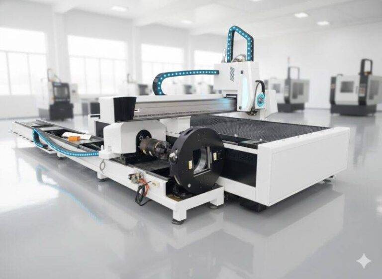
The fabrication of pressure vessels requires rigorous adherence to geometric tolerances and material integrity. Traditional thermal cutting methods often introduce significant heat-affected zones (HAZ) and surface irregularities that necessitate extensive post-processing. The shift toward a dedicated Fiber Laser Cutting Machine represents a move from manual labor-intensive workflows to high-precision, automated systems. This technology leverages short-wavelength laser beams to deliver concentrated energy, resulting in a narrow kerf width and minimal thermal distortion of the shell material.
In industrial engineering terms, the objective is to maximize throughput while minimizing the cost of quality. By utilizing fiber laser sources—ranging from 6kW to 20kW or higher—manufacturers can process carbon steel, stainless steel, and alloy plates with unparalleled speed. Unlike mechanical drilling or legacy thermal processes, the fiber laser maintains a consistent beam quality that ensures the perpendicularity of the cut, which is vital for the subsequent assembly of high-pressure components.
The Role of 3D Vision Positioning Systems
Pressure vessel shells, whether cylindrical or spherical, are rarely perfect geometric entities. Variations in plate rolling, seam welding, and material thickness create deviations from the theoretical CAD model. A 3D Vision Positioning system addresses these real-world variances by utilizing structured light or laser profile scanners to map the actual surface of the vessel in a three-dimensional coordinate system.
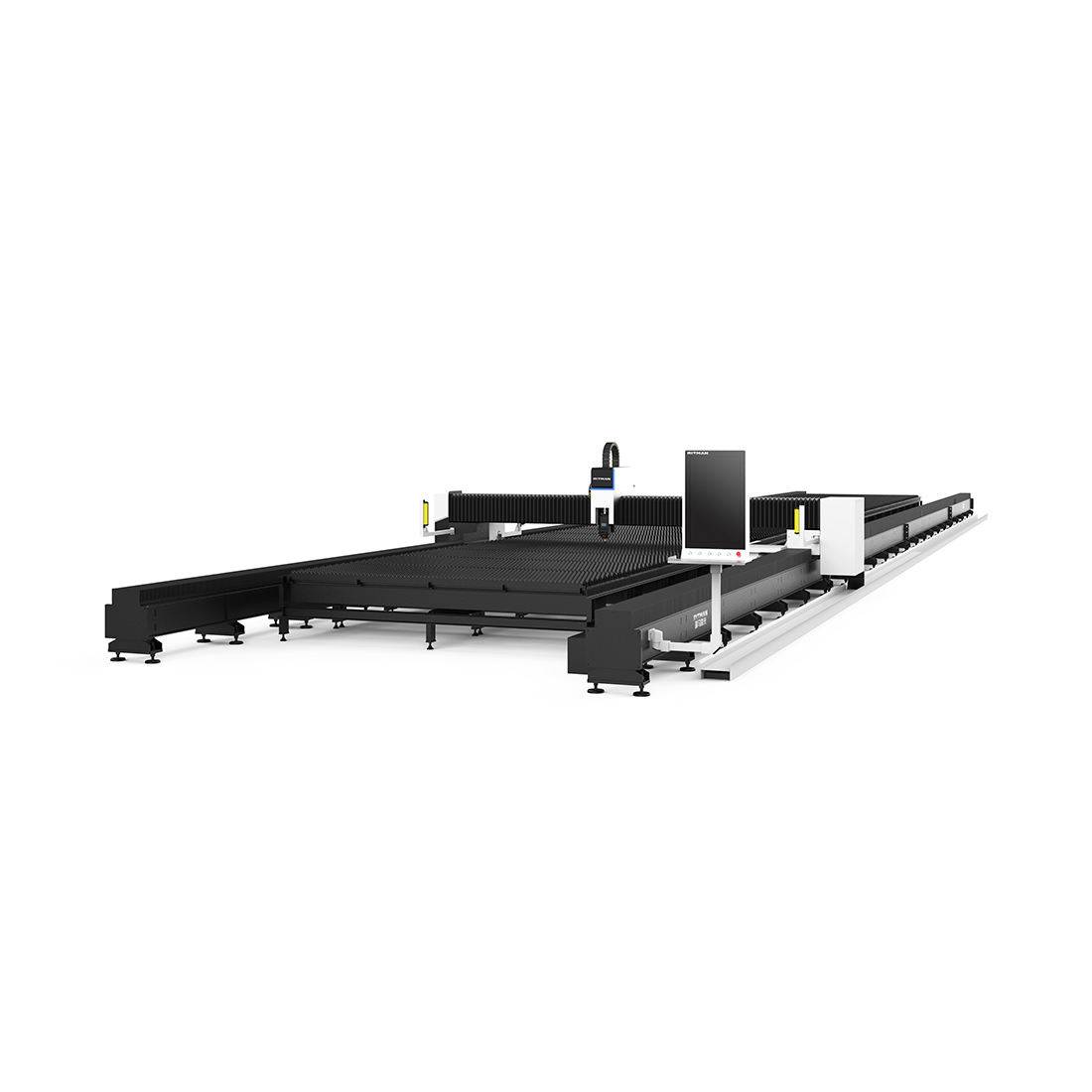
The vision system functions by capturing a point cloud of the vessel’s exterior. This data is processed through localized algorithms that calculate the exact orientation and curvature of the specific area designated for cutting. By syncing this data with the machine’s CNC controller, the laser head can adjust its focal length and nozzle angle in real-time. This dynamic compensation ensures that every hole cut for a nozzle or manway is perfectly aligned with the vessel’s center-line, regardless of any ovality or deformation present in the shell.
Eliminating Secondary Grinding Operations
One of the most significant bottlenecks in Pressure Vessel Fabrication is the requirement for manual grinding. Conventional cutting techniques often leave behind dross, slag, or a hardened oxide layer that must be removed before inspection or assembly. Fiber laser cutting operates at such high frequency and energy density that the resulting edge is typically “weld-ready.”
The high-pressure assist gases (usually Oxygen or Nitrogen) used in fiber laser cutting clear the molten material instantly, leaving a smooth surface finish. For industrial engineers, this translates to a massive reduction in man-hours and a decrease in consumable costs related to abrasive disks. Eliminating the grinding stage also improves the shop floor environment by reducing metallic dust and noise levels, contributing to overall operational safety and efficiency.
The Triad of Efficiency: Punch, Mark, and Cut
A sophisticated fiber laser system for Pressure Vessels is not merely a cutting tool; it is a multi-functional processing center. The system executes three critical tasks in a single setup:
1. Precision Punching and Piercing
The machine utilizes ultra-short pulse cycles to “punch” or pierce the material without creating large craters. This controlled entry is essential when working with thick-walled vessels where traditional piercing might cause blowback or damage the nozzle.
2. Automated Marking and Layout
Before the actual cut, the fiber laser can be tuned to a lower power setting to “mark” the surface. This includes etching heat numbers, part identifiers, or layout lines for structural attachments. This removes the need for manual chalk lines or vibration peening, ensuring that all traceability data is permanently and accurately engraved onto the vessel shell.
3. High-Speed Geometric Cutting
The final phase is the high-speed execution of the required geometry. Whether it is a circular hole for a nozzle or a complex saddle cut for a tangential entry, the laser follows the path corrected by the 3D vision system. The result is a high-tolerance aperture that facilitates a perfect fit-up with the mating component.
Optimizing Automated Hole Cutting for Nozzles
Automated Hole Cutting via fiber laser is particularly advantageous for complex nozzle configurations. In large-scale vessels, nozzles are often placed at various angles—radial, tangential, or lateral. Manually laying out these cuts on a curved surface is prone to human error. The 3D vision system automates the detection of the vessel’s longitudinal and circumferential axes, allowing the CNC software to wrap the 2D cut pattern onto the 3D surface with mathematical precision.
This automation ensures that the “root gap” remains consistent throughout the circumference of the cut. In the context of automated manufacturing, a consistent root gap is the primary requirement for high-quality root pass penetration in subsequent assembly phases. By standardizing the input quality of the cut, the fiber laser system stabilizes the entire production chain.
Technical Specifications and Material Handling
The structural design of these machines usually involves a gantry system or a robotic arm with an extended reach to accommodate large vessel diameters. To maintain the accuracy of the 3D vision system, the motion control hardware must possess high repeatability (typically within ±0.05mm). The integration of a 5-axis or 6-axis cutting head allows for beveling, which is crucial for preparing the edge for V-groove or J-groove configurations.
From an engineering perspective, the fiber laser’s wall-plug efficiency—often exceeding 30%—is significantly higher than CO2 counterparts. This leads to lower operational energy costs. Furthermore, the absence of moving parts within the laser source (unlike turbines in CO2 lasers) reduces maintenance intervals, increasing the Overall Equipment Effectiveness (OEE) of the fabrication facility.
Data Integration and Industry 4.0
Modern fiber laser systems are designed to be nodes within a digital factory. The data collected by the 3D vision sensors can be exported back to the quality management system as a “as-built” digital twin of the vessel. This provides a verifiable record of the hole dimensions and locations, which is often required for ASME or PED certification. The ability to track the cutting parameters (gas pressure, laser power, speed) for every individual cut ensures full traceability, a critical requirement in the oil, gas, and nuclear power sectors.
Conclusion
The implementation of a fiber laser cutting system equipped with 3D Vision positioning transforms pressure vessel production from a craft-based process into a high-precision industrial operation. By combining the three functions of punching, marking, and cutting into a single automated cycle, manufacturers can eliminate redundant steps like manual layout and grinding. The result is a significant reduction in lead times, improved material utilization, and a level of geometric accuracy that is unattainable through traditional mechanical or plasma-based methods. For the industrial engineer, this technology represents the pinnacle of efficiency and quality control in heavy-duty metal fabrication.