Engineering Review: Single Pulse Robotic Arm Welder – Lyon, France
In this article
- Field Engineering Report: Optimization of Single Pulse GMAW in Lyon Tooling Facility
- 1.0 Introduction and Site Context
- 2.0 The Synergy of Robotic Arm Welder Integration and Industrial Automation
- 3.0 Technical Deep-Dive: Tool Steel Welding Parameters
- 4.0 Practical Application: The Lyon Case Study
- 5.0 Lessons Learned and Field Observations
- 6.0 Conclusion
Field Engineering Report: Optimization of Single Pulse GMAW in Lyon Tooling Facility
1.0 Introduction and Site Context
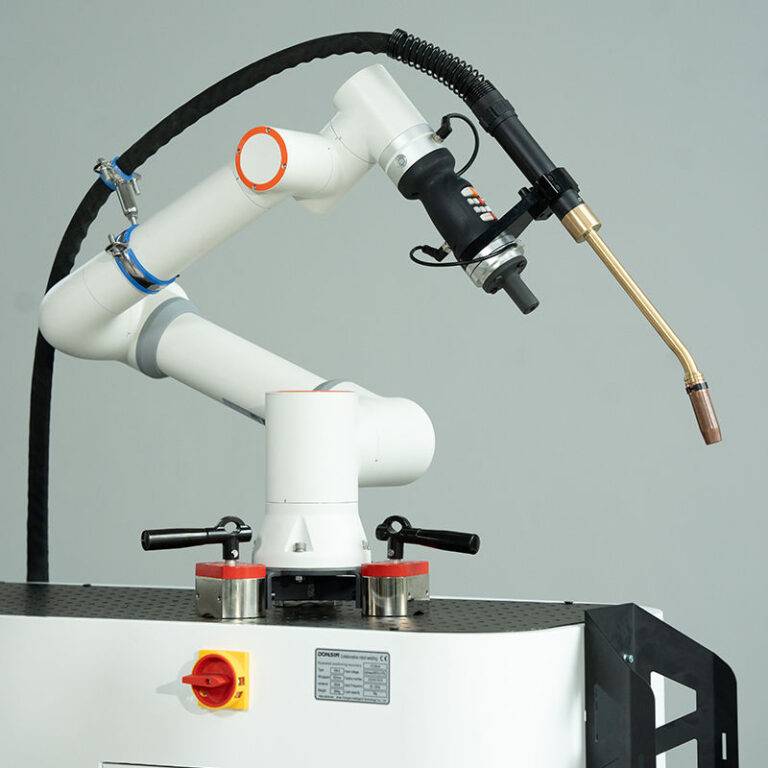
This report summarizes the technical deployment and optimization of a 6-axis Robotic Arm Welder system at our partner facility in Lyon, France. The Lyon industrial corridor, specifically the Rhone-Alpes region, remains a critical hub for high-precision die-making and automotive stamping. Our objective was the integration of Industrial Automation to replace manual cladding processes on large-scale stamping dies, specifically focusing on Tool Steel welding.
The transition from manual Gas Tungsten Arc Welding (GTAW) to a robotic Single Pulse Gas Metal Arc Welding (GMAW-P) setup was necessitated by the need for higher deposition rates and more consistent thermal management. In the context of Tool Steel welding, where carbon equivalency and martensitic transformation temperatures are unforgiving, the precision of a Robotic Arm Welder provides a level of control that manual operators struggle to maintain over an eight-hour shift.
2.0 The Synergy of Robotic Arm Welder Integration and Industrial Automation
The implementation in Lyon demonstrated that a Robotic Arm Welder is not merely a replacement for a human arm; it is the terminal component of a complex Industrial Automation ecosystem. To achieve the tolerances required for European automotive standards, we synchronized the robot controller with a dual-station positioner via a high-speed Profinet interface.
2.1 Logic Synchronization
The Industrial Automation architecture allowed for real-time monitoring of the power source’s primary side. In Lyon, we encountered local grid fluctuations that initially caused arc instability. By integrating a voltage regulation loop into the automation PLC, the Robotic Arm Welder was able to compensate for power drops by modulating wire feed speed dynamically. This level of synergy ensures that the Tool Steel welding bead remains consistent, regardless of external environmental factors.
2.2 Pathing and Tool Center Point (TCP) Calibration
For Tool Steel welding, particularly on complex geometries like shear edges or draw beads, the TCP must be accurate within ±0.08mm. The automation suite included a laser-based wire-searching sensor. Before every weld cycle, the Robotic Arm Welder performs a three-point touch-off. This ensures that the heat-affected zone (HAZ) is precisely mapped, preventing the overheating of adjacent metallurgical structures which is a common failure point in French heavy industry applications.
3.0 Technical Deep-Dive: Tool Steel Welding Parameters
The primary material processed at the Lyon site is H13 (1.2344) tool steel. Welding this material requires a delicate balance of preheat maintenance and controlled energy input to prevent hydrogen-induced cracking and excessive softening of the base metal.
3.1 Pulse Profile Selection
We opted for a Single Pulse regime rather than a standard spray transfer. The Single Pulse waveform allows for one drop of molten metal per pulse, which reduces the overall heat input compared to traditional GMAW. In Tool Steel welding, keeping the interpass temperature below 350°C is critical. The Robotic Arm Welder was programmed with a travel speed of 45 cm/min, which, combined with the pulse frequency, resulted in a cooling rate that favored a fine-grained martensitic structure without the brittleness of untempered martensite.
3.2 Shielding Gas and Consumables
We utilized a ternary gas blend (Ar/He/CO2) sourced from local Lyon suppliers. The inclusion of Helium (25%) increased the thermal conductivity of the arc, allowing for deeper penetration into the tool steel base without needing to increase the amperage to levels that would risk burn-through. The wire used was a matched H13 chemistry, 1.2mm diameter.
4.0 Practical Application: The Lyon Case Study
The workshop in Lyon presented a specific challenge: the repair of a 5-ton stamping die used for aluminum body panels. Manual repair previously took 48 hours of labor, including mandatory cooling periods and post-weld grinding. By leveraging Industrial Automation, we reduced this to 12 hours.
4.1 Thermal Management via Automation
We integrated infrared pyrometers into the Robotic Arm Welder‘s end-of-arm tooling. The Industrial Automation logic was set to “Pause” the welding cycle if the base metal temperature exceeded 400°C. Once the sensors detected the temperature had dropped to the 300°C threshold, the robot automatically resumed the bead sequence. This automated thermal management is impossible to replicate manually with the same degree of accuracy, especially on 24/7 production lines.
4.2 Bead Overlap and Surface Finish
A 50% bead overlap was programmed to ensure a flat topography, minimizing the amount of post-weld machining. The Robotic Arm Welder utilized a “weave” pattern of 3mm width and 2Hz frequency. This technique helped in “washing” the weld metal into the toes of the previous bead, a critical step in Tool Steel welding to avoid stress risers that lead to premature die failure under the high pressures of stamping.
5.0 Lessons Learned and Field Observations
The deployment in Lyon provided several “hard-won” insights that should be applied to future Industrial Automation projects involving high-alloy steels.
5.1 The “Cold Start” Problem
Early in the testing phase, we noticed porosity at the start of each weld segment. Despite the Robotic Arm Welder following the pathing perfectly, the first 10mm of the weld lacked penetration. We resolved this by implementing a “Hot Start” routine in the automation software—increasing the peak current by 15% for the first 0.5 seconds of the arc ignition. This successfully broke the surface tension of the tool steel oxide layer.
5.2 Grounding and High-Frequency Interference
One unforeseen issue was the grounding configuration of the Lyon facility. The high-frequency pulses from the power source were interfering with the robot’s encoder signals, causing intermittent “Path Deviation” errors. We solved this by installing dedicated copper grounding plates for the welding jig and using shielded Cat6e cables for all Industrial Automation communication lines. Never underestimate the impact of electrical noise in a dense industrial environment.
5.3 Wire Feeding Consistency
Tool Steel welding wires are often stiffer than mild steel wires. We observed “chatter” in the wire feeder, which led to arc length fluctuations. We switched to a four-roll drive system on the Robotic Arm Welder and used a ceramic-lined torch cable. This reduced friction significantly, resulting in the rock-steady arc stability required for precision die-cladding.
6.0 Conclusion
The integration of a Robotic Arm Welder at the Lyon site has validated the move toward total Industrial Automation in the tool and die sector. While Tool Steel welding remains one of the most difficult metallurgical challenges in the field, the ability to control heat input, pathing, and interpass cooling through robotic precision significantly outweighs the initial capital expenditure.
For future implementations, I recommend a heavy focus on the pre-welding automation phase—specifically the laser-scanning of the worn die surface. By feeding a 3D point cloud directly into the Robotic Arm Welder‘s controller, we can further optimize deposition paths, reducing material waste and ensuring that the Lyon facility remains at the forefront of European manufacturing excellence.
Prepared by:
Senior Welding Engineer
Field Operations – Lyon Hub