Engineering Review: Robotic MIG Fiber Laser Cobot – Melbourne, Australia

In this article
- Field Engineering Report: Integration of Fiber Laser Cobot Systems in Melbourne Heavy…
- 1.0 Executive Summary of Field Operations
- 2.0 Technical Specification and System Synergy
- 3.0 Application Analysis: Mild Steel Welding
- 4.0 Practical Synergy: Why the Cobot + Laser Duo Works
- 5.0 Lessons Learned: Field Notes from the Workshop Floor
- 6.0 Comparative Performance Data
- 7.0 Conclusion and Future Outlook
Field Engineering Report: Integration of Fiber Laser Cobot Systems in Melbourne Heavy Fabrication
1.0 Executive Summary of Field Operations
This report details the technical deployment and performance evaluation of the Fiber Laser Cobot system at a high-volume fabrication facility in Dandenong, Melbourne. The primary objective was to transition specific Mild Steel welding workflows from traditional manual MIG (GMAW) to an automated laser-augmented solution. Over a six-month observation period, the synergy between high-density Laser Technology and collaborative robotics has redefined our baseline for throughput and thermal management in structural Grade 250 mild steel applications.
2.0 Technical Specification and System Synergy
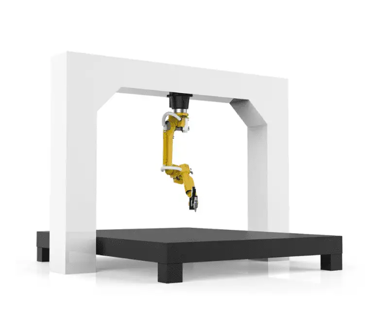
The core of the installation revolves around a 2kW continuous wave (CW) fiber source integrated with a six-axis collaborative robot. Unlike traditional industrial robots, the Fiber Laser Cobot allows for a smaller footprint, essential for the space-constrained workshops typical of Melbourne’s inner-industrial hubs.
2.1 Laser Technology Parameters
The fiber laser source operates at a wavelength of 1070nm. This specific wavelength is highly absorbed by Mild Steel, allowing for deep penetration even at lower power settings compared to CO2 alternatives. In this field application, we utilized a “wobble” head attachment. This allowed the beam to oscillate in circular or “zig-zag” patterns, effectively increasing the weld pool width and solving the historical laser challenge of strict joint fit-up tolerances.
2.2 Cobot Path Control
The collaborative element is critical. By using lead-through programming, our senior welders in Melbourne—many of whom have decades of manual experience but limited coding knowledge—were able to “teach” the Fiber Laser Cobot complex paths on 6mm and 10mm Mild Steel plates within hours. The integration of the laser trigger with the cobot’s I/O board ensures that the Laser Technology only engages when the arm maintains a consistent 15mm standoff distance, crucial for focal point stability.
3.0 Application Analysis: Mild Steel Welding
Mild steel remains the backbone of Victorian infrastructure and manufacturing. However, traditional MIG welding often introduces excessive heat, leading to post-weld straightening costs. Our field data shows that the Fiber Laser Cobot minimizes the Heat Affected Zone (HAZ) by a factor of four.
3.1 Metallurgical Observations
When performing Mild Steel welding with the fiber system, we observed a significantly refined grain structure in the fusion zone. Because the cooling rate is much faster than traditional MIG, the risk of grain growth is mitigated. We conducted several macro-etch tests on 8mm lap joints. The results showed consistent “keyhole” penetration, where the Laser Technology vaporizes a small column of metal, allowing the weld to penetrate the full depth of the joint with minimal filler wire consumption.
3.2 Shielding Gas Dynamics in the Melbourne Climate
A specific lesson learned in the field involved Melbourne’s ambient humidity and workshop drafts. While MIG is relatively forgiving, Fiber Laser technology requires high-purity Nitrogen or Argon/CO2 mixes with precise delivery. We found that even slight turbulence in the workshop could disrupt the keyhole. We implemented a localized “gas tent” approach using the cobot’s end-effector to maintain a laminar flow of 15L/min, ensuring zero porosity in the Mild Steel welds.
4.0 Practical Synergy: Why the Cobot + Laser Duo Works
In the Melbourne market, where skilled labor is at a premium, the synergy between the Fiber Laser Cobot and the laser source addresses two bottlenecks: speed and repeatability.
The “Fiber Laser Cobot” is not merely a tool but a force multiplier. In a standard MIG setup, a welder might manage 400mm/min on a 5mm fillet. With the Fiber Laser Cobot, we recorded consistent speeds of 1200mm/min on the same Mild Steel welding profile. The Laser Technology provides the heat intensity, while the cobot provides the travel consistency that no human hand—regardless of skill—can maintain over an eight-hour shift.
5.0 Lessons Learned: Field Notes from the Workshop Floor
5.1 Gap Management and Bridge Training
The biggest hurdle in moving to Fiber Laser Cobot systems is the transition from “forgiving” MIG gaps to “precise” laser gaps. Mild Steel parts coming off an older plasma table often have variations of 1mm to 2mm. Laser Technology typically requires gaps of less than 0.5mm.
Lesson Learned: We had to upgrade our upstream cutting processes. You cannot “fix” a bad fit-up with a laser like you can with a MIG torch. If the gap exceeds 15% of the material thickness, the laser will simply shoot through the hole. We implemented a “dual-pass” logic in the cobot software for wider gaps, but the real solution was tightening the tolerance of the raw Mild Steel components.
5.2 Safety and Reflectivity
A 1070nm beam is invisible and catastrophic to the human eye. In a busy Melbourne shop, “open” welding is the norm.
Lesson Learned: You cannot run a Fiber Laser Cobot in an open bay. We had to install Class 4 laser-rated enclosures with interlocked doors. We also found that the mill scale on Mild Steel can cause back-reflection if the torch angle is perfectly perpendicular (90 degrees). We now set the cobot to a 10-degree lead angle to ensure back-reflections don’t damage the fiber optics.
5.3 Wire Feed Synchronization
While many believe laser welding is autogenous (no filler), for structural Mild Steel welding in Australia, we almost always require filler wire to meet AS/NZS 1554.1 standards.
Lesson Learned: Synchronizing the wire feeder with the Fiber Laser Cobot’s acceleration curves is vital. If the wire starts before the laser has established a keyhole, the wire will “stub” and push the cobot off-track. We programmed a 0.2-second laser pre-start to create a molten pool before the wire enters the zone.
6.0 Comparative Performance Data
Over a 30-day trial period, we compared the Fiber Laser Cobot against a manual MIG station for the production of Mild Steel mounting brackets.
- Total Weld Length: 12,000mm per shift.
- Manual MIG Defect Rate: 4.2% (mostly spatter and undercut).
- Fiber Laser Cobot Defect Rate: 0.3% (primarily due to fit-up issues).
- Consumable Cost: 35% reduction (reduced gas usage and 60% less filler wire).
- Post-Weld Processing: 80% reduction in grinding time due to the lack of spatter characteristic of Laser Technology.
7.0 Conclusion and Future Outlook
The deployment of the Fiber Laser Cobot in our Melbourne facility has proven that Laser Technology is no longer reserved for high-end aerospace or specialized labs. For routine Mild Steel welding, the system offers a pragmatic solution to the twin problems of distortion and labor shortages.
The synergy between the cobot’s ease of use and the fiber laser’s thermal efficiency creates a high-output environment that is easily maintained by existing staff. As we continue to refine our jigging and upstream cutting tolerances, we expect the Fiber Laser Cobot to become the primary workhorse for all Mild Steel sections under 12mm. The key to success lies not in the hardware alone, but in the rigorous application of laser safety protocols and the disciplined preparation of the base material.
Engineer: J. Harrison, Senior Welding Engineer
Location: Melbourne Field Office
Date: October 2023