Field Report: Optimization of Automated MAG Welding Cell for Structural Steel Fabrication
1. Project Overview and Site Conditions
This report details the operational commissioning and performance optimization of a high-capacity Automated MAG Welding Cell at a heavy-duty fabrication facility in the Gulf Coast region of Texas, USA. The facility specializes in structural steel welding for energy infrastructure and large-scale commercial frameworks. Given the high ambient temperatures and humidity levels characteristic of the Texas coast, the integration of advanced Arc Welding Solutions was required to maintain metallurgical integrity and equipment duty cycles.
The transition from manual MIG (GMAW) stations to a robotic MAG (Metal Active Gas) environment was driven by the need for increased deposition rates and tighter adherence to AWS D1.1 standards. Manual processes were seeing a 15-20% rejection rate on UT (Ultrasonic Testing) due to intermittent lack of fusion at the start/stop points of long-span girders. The automated solution was implemented to provide the consistency that human operators, despite their skill, struggle to maintain over 10-hour shifts in 100°F+ workshop conditions.
2. The Automated MAG Welding Cell: Technical Configuration
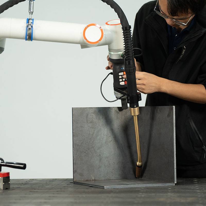
The core of the installation is a dual-station H-frame Automated MAG Welding Cell equipped with a six-axis industrial manipulator and a 500-ampere inverter-based power source. For structural steel welding, we opted for a MAG configuration rather than a pure MIG setup. Utilizing a shielding gas mix of 80% Argon and 20% CO2 provides the necessary “active” component to ensure deep penetration into the 1-inch A36 carbon steel plates commonly processed at this site.
2.1. Tooling and Positioning
The cell utilizes a head-and-tailstock positioner capable of rotating 3,000 kg loads. In the Texas workshop, thermal expansion of long structural members can lead to fit-up variances of up to 3mm. To combat this, the Automated MAG Welding Cell was integrated with high-speed touch sensing and laser-based seam tracking. This allows the robot to “search” for the weld joint before striking the arc, adjusting its path in real-time to accommodate the physical realities of large-scale structural steel welding.
3. Implementing Advanced Arc Welding Solutions
The term Arc Welding Solutions is often used as a catch-all, but in this field application, it refers specifically to the synergy between the power source software and the physical delivery of the consumable. For this Texas project, we implemented a “Modified Short Circuit” process for the root pass and a “Pulsed Spray Transfer” for the fill and cap passes.
3.1. Waveform Control and Spatter Mitigation
One of the primary Arc Welding Solutions deployed was a proprietary waveform that minimizes heat input while maximizing deposition. In structural steel welding, excessive heat leads to warping and grain growth in the heat-affected zone (HAZ). By utilizing an automated system, we achieved a travel speed of 45 inches per minute on 1/2-inch fillet welds, which is nearly double the speed of manual operators. The reduction in spatter—achieved through precise pulsed control—reduced post-weld grinding time by 80%, a critical metric for shop throughput.
3.2. Consumable Management
We encountered an early issue with “wire flip” in the 60lb bulk drums. In the humid Texas environment, even slight oxidation on the wire surface can increase friction in the liners. Our solution was the installation of a localized dehumidification unit for the wire storage area and the use of chrome-moly liners to ensure smooth delivery to the Automated MAG Welding Cell. Constant wire feed speed is the backbone of arc stability; without it, the most expensive robot in the world is just a paperweight.
4. Structural Steel Welding Challenges in a Texas Environment
Structural steel welding in the southern United States presents unique environmental variables. High humidity affects the hydrogen levels in the weld pool, and extreme ambient heat stresses the internal cooling systems of the welding power sources.
4.1. Thermal Management of the Cell
During the July-August period, the internal cabinet temperature of the Automated MAG Welding Cell reached 115°F. We observed intermittent controller hang-ups. The “lesson learned” here was the necessity of secondary industrial AC units for the control cabinets. While the Arc Welding Solutions were technically sound, the hardware environment required “Texas-proofing.” Once the ambient cooling was stabilized, the system maintained a 95% up-time over three shifts.
4.2. Handling Heavy Sections
In structural steel welding, the mass of the workpiece acts as a massive heat sink. When welding thick-walled H-beams, we programmed a pre-heat cycle into the cell’s logic. The robot uses an induction heating torch attachment—part of our integrated Arc Welding Solutions—to bring the joint to 250°F before the MAG torch initiates. This ensures that the cooling rate of the weld metal is slow enough to prevent martensitic transformation and subsequent cracking.
5. Synergy: The Intersection of Automation and Process Expertise
The real-world success of this site stems from the synergy between the Automated MAG Welding Cell and the specific Arc Welding Solutions tailored for structural steel welding. You cannot simply buy a robot and expect it to weld structural steel perfectly out of the box. It requires a deep understanding of the metallurgy involved.
5.1. Data-Driven Quality Assurance
The integrated system now logs every weld parameter—current, voltage, gas flow, and travel speed—to a central cloud server. In the event of a UT failure, we can backtrack to the exact second that weld was made to see if a gas surge or a voltage drop occurred. This level of accountability is impossible with manual welding. For Texas fab shops looking to compete on a global scale, this data is as valuable as the steel itself.
5.2. Welder to Operator Transition
A significant “field lesson” was the human element. The best operators for the Automated MAG Welding Cell were not the computer science graduates, but the veteran structural steel welding experts. They knew what a “good” arc sounded like. By teaching these welders how to tweak the Arc Welding Solutions (adjusting trim, wire feed offsets, etc.), we empowered the workforce rather than replacing it. Their “eye” for the puddle, combined with the robot’s “arm” for consistency, created a formidable production unit.
6. Lessons Learned and Final Recommendations
Reflecting on the commissioning phase of this Texas project, several key technical takeaways emerge for any engineer looking to deploy an Automated MAG Welding Cell in a heavy industrial setting:
- Grounding is Non-Negotiable: High-frequency interference from the Arc Welding Solutions power source can play havoc with robot encoders. We had to implement a dedicated copper grounding grid for the cell, separate from the building’s main electrical ground, to eliminate “ghost” errors in the motion path.
- Gas Shielding Strategy: In large open-bay shops in Texas, cross-drafts are common. We increased the gas nozzle diameter and implemented a “gas lens” effect within the robotic torch to maintain laminar flow. Even a 5mph breeze can strip the MAG shielding gas, leading to porosity in structural steel welding.
- Predictive Maintenance: The contact tip is the most common point of failure. We implemented an automatic tip-changing routine every 200 meters of weld. This prevents the “burn-back” issues that often plague automated systems during high-amperage cycles.
7. Conclusion
The deployment of the Automated MAG Welding Cell has transformed the production capacity of this Texas facility. By focusing on robust Arc Welding Solutions—specifically those that address the environmental and metallurgical demands of structural steel welding—we have achieved a 40% increase in throughput and a 60% reduction in rework. The investment in automation is not merely about speed; it is about the precision of the arc and the reliability of the joint in the most demanding structural applications.
As we move forward, the focus will shift toward AI-driven predictive analytics, using the data currently being harvested to predict component failure before it occurs. For now, the cell stands as a benchmark for automated structural fabrication in the region.
Report Prepared By:
Senior Welding Engineer, Texas Field Division
Date: October 2023
-

LT240S tube laser cutting machine
-
LT120S tube laser cutting machine
-
Sale

Tank Fillet Welding Machine
Original price was: $1,000.00.$900.00Current price is: $900.00. -
Sale

MAK100 tube laser cutting machine
Original price was: $5,500.00.$5,000.00Current price is: $5,000.00. -

portable plasma air cutting machine
$1,200.00 -

2in1 fiber laser cutting machine
-

Air cooling Laser welding machine
-

HF h beam laser cutting machine
-

LT240 laser cutting machine
-

Laser welding machine
-

Cobot Welding Station
-

Gantry welding robot solution
-

Tracked Wheeled AGV Welding robot
-

LFH6020 Fiber laser cutting machine
-
LFP6020
-

robotic welidng machine
Advanced Fiber Laser Tube Processing Technology
Our CNC Fiber Laser Tube Cutting systems revolutionize metal fabrication by integrating high-precision cutting, punching, and profiling into a single automated workflow. Designed for versatility, this technology handles a wide array of profiles including Round, Square, Rectangular, and Oval tubes, as well as complex L-shaped and U-shaped channels.
- Precision Punching: High-speed hole punching with micron-level accuracy, eliminating the need for mechanical drilling or die-stamping.
- Complex Profiling: Advanced 3D pathing allows for intricate interlocking joints and specialized notch cuts, ideal for structural frames.
- High Material Efficiency: Intelligent nesting software minimizes scrap, reducing raw material costs across large production runs.
- Clean Finish: Delivers oxide-free, burr-free edges that require zero secondary grinding before welding.

Seamlessly processing multiple profiles with consistent precision.
Global Delivery & Logistics


From our high-tech manufacturing facility directly to your global site. PCL WeldCut ensures secure packaging, professional handling, and reliable international logistics to safeguard your equipment throughout the entire journey.