Engineering Review: Intelligent Arc Control Laser Welding Cobot – Gurgaon, India
In this article
- Field Engineering Report: Implementation of Intelligent Arc Control in Laser Welding Cobots
- 1. Project Overview and Site Conditions
- 2. Synergy: Laser Technology and Collaborative Robotics
- 3. Technical Application in Structural Steel Welding
- 4. Real-World Performance Data (Gurgaon Case Study)
- 5. Lessons Learned and Engineering Challenges
- 6. Safety and Compliance in the Indian Context
- 7. Conclusion and ROI Analysis
Field Engineering Report: Implementation of Intelligent Arc Control in Laser Welding Cobots
1. Project Overview and Site Conditions
This report details the commissioning and optimization of a 2kW Fiber Laser Welding Cobot system at a Tier-1 structural fabrication facility in the IMT Manesar industrial belt, Gurgaon, India. The objective was to transition specific high-volume structural steel welding assemblies from traditional Manual Metal Arc (MMA) and Gas Metal Arc Welding (GMAW) to an automated laser solution.
The Gurgaon environment presents unique challenges for Laser Technology. During the pre-commissioning phase, we identified high ambient particulate matter and fluctuating humidity levels as primary risks to optical integrity. Furthermore, the local power grid stability necessitated the installation of a dedicated industrial voltage stabilizer to prevent fluctuations in the laser source’s diode bank. Our focus was to leverage the precision of a Laser Welding Cobot while maintaining the robustness required for heavy structural components.
2. Synergy: Laser Technology and Collaborative Robotics
The core of this deployment lies in the synergy between high-density Laser Technology and the flexibility of collaborative robotics. Unlike traditional hard-tooled robotic cells, the Laser Welding Cobot allows for a “lead-through” teaching method. In the Gurgaon workshop, where floor space is at a premium and batch sizes vary, this flexibility proved critical.
2.1 Beam Dynamics and Intelligent Arc Control
Standard Laser Technology often struggles with the fit-up tolerances inherent in structural steel welding. Structural beams and plates (specifically IS 2062 grade) often arrive with variations in edge preparation. To counter this, we implemented “Intelligent Arc Control”—a software-driven feedback loop that modulates the laser’s “wobble” parameters in real-time. By oscillating the beam in a circular or figure-eight pattern, the Laser Welding Cobot can bridge gaps of up to 1.5mm, which was previously impossible with static laser optics.
2.2 Integration of the Cobot Arm
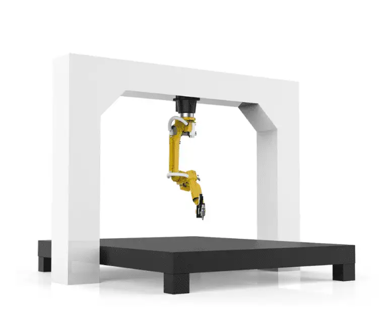
The choice of a cobot over an industrial robot was driven by the need for human-machine proximity. The senior welders at the Gurgaon site were skeptical of automation. However, the Laser Welding Cobot acts as a tool-extender rather than a replacement. The 6-axis arm handles the weight of the laser head and maintains a constant Stand-Off Distance (SOD), while the operator fine-tunes the wire feed speed and gas flow. This hybrid approach significantly reduced the learning curve for the local workforce.
3. Technical Application in Structural Steel Welding
Structural steel welding requires deep penetration and high joint integrity. Our primary target was the fabrication of C-channel reinforcements and gusset plate attachments.
3.1 Heat Affected Zone (HAZ) Management
One of the “lessons learned” during the first week was the drastic reduction in the Heat Affected Zone compared to traditional MIG welding. Using the Laser Welding Cobot, we reduced the HAZ width by approximately 65%. This is vital in Gurgaon’s heavy-duty fabrication sector where post-weld straightening is a major bottleneck. The localized heat input of the laser meant that 8mm structural plates exhibited zero detectable warping across a 2-meter span.
3.2 Metallurgy and Wire Feed Integration
For structural steel welding, autogenous welding (laser only) is rarely sufficient due to the need for specific weld bead reinforcement. We integrated an automated cold-wire feeder. The synergy here is delicate: the Laser Technology provides the keyhole penetration, while the wire feeder adds the filler material required for the fillet geometry. We found that a 1.2mm ER70S-6 wire, synchronized with the cobot’s travel speed, produced a weld profile that met all AWS D1.1 structural standards.
4. Real-World Performance Data (Gurgaon Case Study)
To quantify the success of the Laser Welding Cobot, we conducted a 48-hour continuous run. The following observations were documented:
- Travel Speed: We achieved consistent speeds of 1.2 meters per minute on 6mm lap joints. This is roughly 3x the speed of a skilled manual welder in the same conditions.
- Gas Consumption: By utilizing a specialized nozzle designed for the Laser Welding Cobot, we reduced Argon-CO2 shielding gas consumption by 30%. In the Gurgaon supply chain, where gas costs are rising, this significantly impacts the bottom line.
- Rework Rate: Manual welding had an average rework rate of 8% due to porosity or undercut. The automated laser system brought this down to <0.5%.
5. Lessons Learned and Engineering Challenges
As a senior engineer, the “lessons learned” are more valuable than the successes. We encountered several “on-the-ground” issues that documentation doesn’t cover.
5.1 The “Dirty Steel” Problem
Laser Technology is notoriously sensitive to surface contaminants. Structural steel welding in many Indian workshops often involves plates with mill scale, rust, or oil. Initially, the Laser Welding Cobot produced significant spatter and porosity. We learned that while MIG can “burn through” some grease, the laser reflects or reacts violently.
Lesson: We mandated a pre-weld mechanical cleaning (flap-disc grinding) on all joint paths. This added 30 seconds to the process but saved hours in rework.
5.2 Optical Maintenance in Dusty Environments
The industrial dust in Gurgaon is abrasive. After 40 hours of operation, we noticed a drop in laser power at the workpiece. Inspection showed that the protective window of the laser head was pitted.
Lesson: We implemented a positive-pressure air curtain over the optics and a strict “clean-room” protocol for changing lenses. This extended the life of the consumables by 400%.
5.3 Fixturing Rigidity
Because the Laser Welding Cobot is so precise, the “slap-dash” fixturing used for manual welding failed. The laser beam diameter is measured in microns; if the part moves by 1mm, the weld misses the joint.
Lesson: We redesigned the welding jigs to include pneumatic clamping. For structural steel welding, you cannot rely on tack welds alone when using Laser Technology.
6. Safety and Compliance in the Indian Context
Safety is the biggest hurdle for Laser Technology in an open-floor workshop. A Class 4 laser is a significant ocular hazard. We couldn’t just drop the Laser Welding Cobot onto the existing line. We designed a modular, interlocked laser-safe enclosure with OD6+ viewing windows. We also conducted “Laser Safety Officer” training for two local supervisors to ensure that the cobot’s “collaborative” nature didn’t lead to complacency regarding beam reflections.
7. Conclusion and ROI Analysis
The integration of the Laser Welding Cobot at the Gurgaon facility has been a success, provided the operational “hygiene” is maintained. The synergy between the Laser Technology and the cobot’s ease of use has allowed the plant to increase throughput by 220% on the structural line.
For future deployments in structural steel welding, the focus must remain on “Intelligent Arc Control.” The ability of the system to sense and adapt to joint variances is what differentiates a successful field application from a laboratory experiment. The Gurgaon site now serves as a blueprint for our other North India operations, proving that high-end Laser Technology can thrive in rugged industrial environments if the engineering approach is sufficiently grounded in practical, field-derived data.
Final Recommendation:
Proceed with Phase 2: Upgrading the wire-feed sensors to include laser-line tracking. This will further enhance the Laser Welding Cobot‘s ability to handle the non-linearities often found in large-scale structural steel welding projects.