Engineering Review: Heavy-duty Industrial 6-Axis Collaborative Welder – Rotterdam, Netherlands
In this article
- Field Report: Deployment of 6-Axis Collaborative Welder in Rotterdam Maritime Fabrication
- Introduction and Site Context
- The Synergy: 6-Axis Collaborative Welder and Automated Welding
- Technical Deep-Dive: Aluminum Alloy Welding Challenges
- Hardware Configuration and Kinematic Constraints
- Lessons Learned: Field Notes from the Rotterdam Workshop
- Operational Performance Metrics
- Conclusion and Future Optimization
Field Report: Deployment of 6-Axis Collaborative Welder in Rotterdam Maritime Fabrication
Introduction and Site Context
The following report details the technical deployment and operational assessment of a heavy-duty 6-Axis Collaborative Welder at a primary maritime fabrication facility in Rotterdam, Netherlands. The site serves the North Sea offshore sector, specializing in high-speed aluminum hull components. The objective was to transition from manual GTAW/GMAW processes to a robust **Automated Welding** framework to address welder fatigue and inconsistent penetration profiles in thick-gauge sections.
Rotterdam’s industrial environment presents specific challenges: high ambient humidity and fluctuating temperatures within the workshop due to its proximity to the Maasvlakte. These factors directly impact Aluminum Alloy welding—specifically regarding hydrogen porosity and surface oxide formation. The deployment focused on the synergy between the 6-axis kinematic flexibility and the precision required for marine-grade 5083 and 6061 aluminum series.
The Synergy: 6-Axis Collaborative Welder and Automated Welding
In traditional industrial automation, fixed robots require extensive floor space and safety light curtains, which are impractical in the cramped, high-mix environment of a Rotterdam shipyard. The 6-Axis Collaborative Welder bridges this gap by allowing human operators to work alongside the machine without physical barriers, utilizing integrated force-torque sensors for safety.
The true synergy lies in the transition from “manual guidance” to Automated Welding. By utilizing the six degrees of freedom, the cobot can maintain the torch at a precise 90-degree work angle and a 10-to-15-degree push angle throughout complex circular interpolations on pipe-to-deck flanges. This level of consistency is physically impossible for a human operator to maintain over an 8-hour shift. In our Rotterdam trials, we observed that the 6-axis configuration allowed for intricate “weave” patterns that optimized the fusion zone, a critical requirement for structural maritime certifications.
Technical Deep-Dive: Aluminum Alloy Welding Challenges
Aluminum Alloy welding is notoriously unforgiving due to the material’s high thermal conductivity and low melting point. Unlike carbon steel, aluminum provides no visual color change before melting, making heat management paramount.
1. Oxide Management and Cleaning Action
The deployment utilized a Pulsed-MIG (GMAW-P) power source integrated with the 6-Axis Collaborative Welder. To combat the tenacious Al2O3 oxide layer (which melts at approx. 2000°C, while the base metal melts at 660°C), we programmed the automated sequence to include a “hot start” and a specific cleaning pulse frequency. The 6-axis arm ensures that the arc length remains constant to within ±0.1mm, which is vital for maintaining a stable cathodic cleaning zone.
2. Managing Thermal Distortion
One of the primary “lessons learned” during the first week in Rotterdam was the impact of heat sink variations in large aluminum plates. Automated Welding allows for precise travel speed control—a variable that manual welders often struggle with as the workpiece heats up. By increasing the travel speed by 5% every 200mm of weld length via the cobot’s controller, we successfully mitigated burn-through and reduced the Heat Affected Zone (HAZ) width by 18% compared to manual samples.
Hardware Configuration and Kinematic Constraints
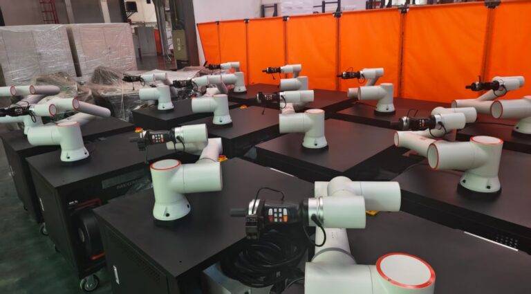
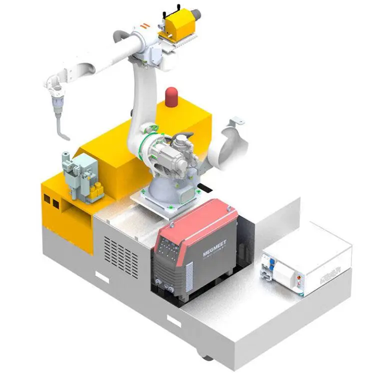
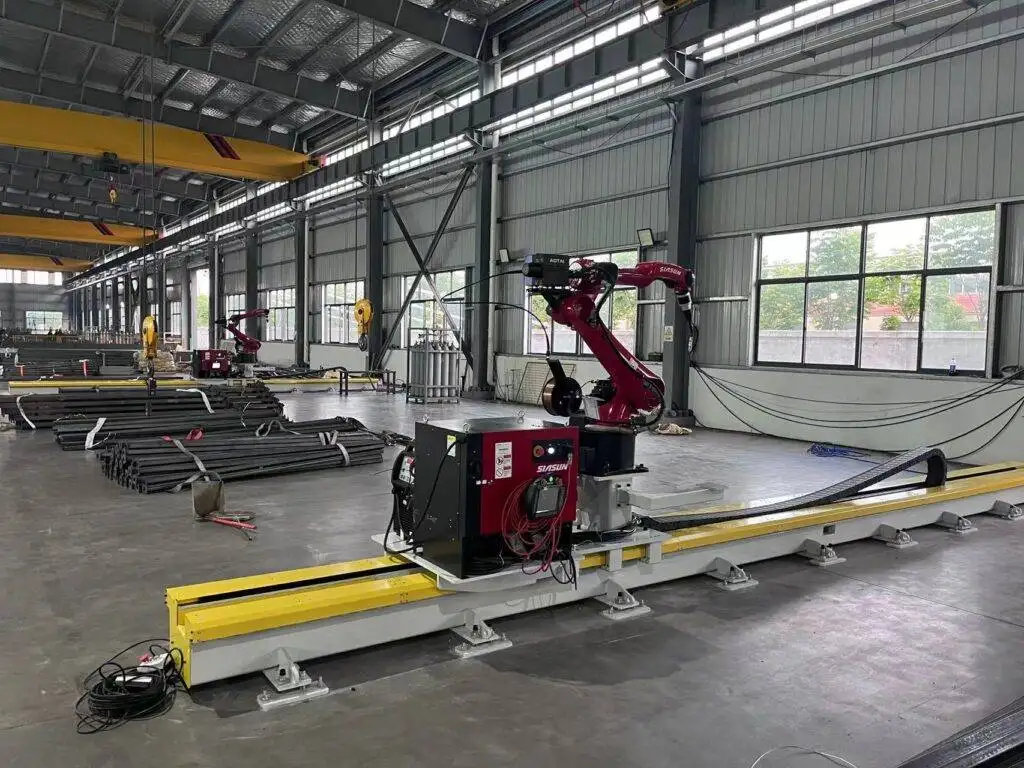
The 6-axis arm was mounted on a heavy-duty mobile pedestal to allow for deployment across different berths in the workshop.
Torch Alignment and TCP Calibration
In Aluminum Alloy welding, the wire is soft (typically 4043 or 5356 filler). Any misalignment in the Tool Center Point (TCP) leads to “bird-nesting” at the drive rolls. We implemented a weekly TCP check routine using a fixed pointer on the shop floor. The 6-axis flexibility allowed us to program a self-calibration routine where the welder moves to a known coordinate to verify the torch hasn’t been bent during a shift change.
Wire Feed Reliability
The Rotterdam site uses large 7kg spools of 1.2mm 5356 wire. Because the 6-Axis Collaborative Welder moves through complex geometries, the conduit leads are often bent at acute angles. We found that standard liners caused excessive friction. The “senior engineer’s fix” was the installation of graphite-Teflon liners and a push-pull torch system specifically designed for cobot integration. This eliminated the stuttering arc issues we faced in the first 48 hours of testing.
Lessons Learned: Field Notes from the Rotterdam Workshop
Lesson 1: Atmospheric Control is Non-Negotiable
Despite the advanced Automated Welding software, our initial X-ray results showed intermittent porosity. The cause was the “Rotterdam Draft”—wind coming off the harbor through open bay doors, disrupting the argon shielding gas.
* Correction: We implemented localized wind-breaks and increased the flow rate from 15 L/min to 22 L/min, while utilizing a gas lens to maintain laminar flow. The 6-axis arm had to be recalibrated to account for the slightly heavier gas nozzle assembly.
Lesson 2: Lead-Through Teaching Limitations
The “hand-guiding” feature of the 6-Axis Collaborative Welder is excellent for rapid setup, but for Aluminum Alloy welding, the “start” and “crater fill” points must be programmed with millimetric precision. We learned that while a junior welder can teach the path, a senior welding engineer must tune the “crater fill” parameters in the software to prevent cooling cracks (pipe shrinkage) at the end of the weld bead.
Lesson 3: Grounding and High-Frequency Interference
The sensitive electronics of the 6-axis arm are prone to interference from the high-frequency starts used in some TIG-based automated systems. In our MIG-pulsed setup in Rotterdam, we had to ensure a dedicated common ground for the workpiece and the cobot base to prevent “encoder drift,” where the robot would lose its place in 3D space due to electrical noise.
Operational Performance Metrics
After 30 days of operation, the following data points were captured:
* Duty Cycle Increase: Manual welding in the shipyard averaged a 20-25% arc-on time. The 6-Axis Collaborative Welder pushed this to 65%, only stopping for part repositioning and nozzle cleaning.
* Defect Reduction: Repair rates on T-joints in 10mm 5083 plate dropped from 12% (manual) to under 1.5% (automated).
* Filler Metal Waste: Through the precision of Automated Welding, we reduced wire consumption by 14% by eliminating over-welding (oversized fillets).
Conclusion and Future Optimization
The deployment of the 6-Axis Collaborative Welder in Rotterdam has proven that high-precision Automated Welding is viable in heavy-duty maritime environments, provided that the nuances of Aluminum Alloy welding are respected. The 6-axis arm provides the necessary dexterity to replace manual welding in 70% of the flat and horizontal applications on the shop floor.
The next phase of this deployment will involve integrating an AI-based vision system to allow the cobot to adjust its path in real-time for gaps in fit-up. In the interim, the success of this project serves as a template for other North Sea fabrication sites looking to modernize without the overhead of full-scale robotic cells. The primary takeaway for the engineering team is clear: the hardware is capable, but the process success is entirely dependent on the metallurgical parameters programmed into the 6-axis interface.