Field Engineering Report: Implementation of 2000W MIG/MAG Welding Robot (Site: London, UK)
1.0 Executive Summary of Field Deployment
This report details the operational commissioning and performance calibration of a 2000W MIG/MAG Welding Robot at a specialized fabrication facility in East London. The objective was to integrate high-efficiency Arc Welding Solutions into a production line primarily handling thin-gauge structural components and specialized aerospace-grade Titanium welding.
The London site presented specific logistical constraints, primarily high-density floor utilization and strict UK HSE (Health and Safety Executive) regulations regarding particulate emissions and UV shielding. Over a 14-day deployment period, the engineering team focused on the synergy between the robotic motion controller and the power source logic to ensure weld integrity met ISO 5817 Level B standards.
2.0 Technical Specification and Infrastructure Synergy
2.1 The MIG/MAG Welding Robot Architecture
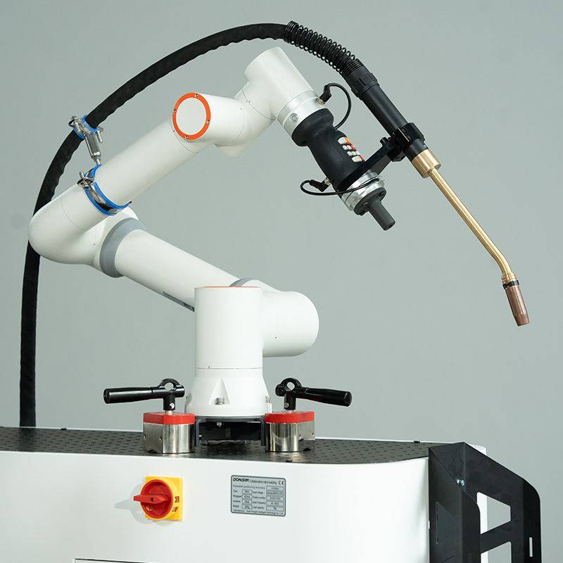
The 2000W power source utilized in this cell is a high-frequency inverter-based system. While 2kW is often considered mid-range, for the precision required in London’s tech-heavy fabrication sector, it provides the ideal thermal envelope for high-speed MAG (Metal Active Gas) welding on carbon steels and MIG (Metal Inert Gas) on non-ferrous alloys. The MIG/MAG Welding Robot is a 6-axis articulated arm with a payload capacity of 10kg, optimized for the torch weight and the integrated wire-feed assembly.
A critical lesson learned during the first 48 hours of installation involved the synchronization of the robot’s TCP (Tool Center Point) with the wire-feed speed. At 2000W, the arc stability is highly sensitive to contact tip-to-work distance (CTWD). We found that a CTWD of 12mm ±1mm was required to prevent spatter buildup during the MAG process on S355 structural steel.
2.2 Integrating Arc Welding Solutions
The term “Arc Welding Solutions” in this context refers to the holistic ecosystem: the power source, the shielding gas delivery system, and the real-time feedback sensors. In the London workshop, we utilized a mixture of 80% Argon and 20% CO2 for the MAG sequences. However, the true technical challenge lay in the automated “search and track” functionality of the arc solution.
By leveraging the Arc Welding Solutions software, we programmed the robot to perform “Touch Sensing” to locate the workpiece before arcing. This is crucial in London-based shops where material storage space is limited, and minor variations in jigging often occur due to floor vibrations from nearby heavy transit (the Jubilee Line extension proximity, in this instance). The synergy between the MIG/MAG Welding Robot and the sensor suite allowed for a 15% reduction in scrap rates compared to manual intervention.
3.0 Titanium Welding: The Critical Case Study
3.1 Material Sensitivity and Shielding Challenges
The London facility recently secured a contract for Grade 2 and Grade 5 titanium exhaust components. Titanium welding using a MIG/MAG Welding Robot is notoriously difficult due to the metal’s high reactivity with oxygen and nitrogen at temperatures above 427°C. The “lessons learned” here were hard-won.
Standard Arc Welding Solutions for steel are insufficient for Titanium welding. We had to retrofit the robotic torch with a customized trailing shield—a secondary gas chamber that follows the torch to provide a laminar flow of 99.999% pure Argon over the cooling weld bead. Without this, the titanium would undergo atmospheric contamination, resulting in a brittle, “straw” or “blue” colored weld, both of which are grounds for immediate rejection in high-performance applications.
3.2 Parameter Optimization for Ti-Alloys
Using the 2000W source, we operated in a pulsed-MIG mode. Pulsing allows for a lower average heat input while maintaining high peak current to ensure deep penetration. This is vital for Titanium welding to minimize the Heat Affected Zone (HAZ). We established a pulse frequency of 120Hz with a background current of 45A. This prevented “burn-through” on 1.5mm Ti-sheets while ensuring the MIG/MAG Welding Robot maintained a travel speed of 450mm/min.
4.0 Operational Field Data and Logic
4.1 Power Management in a London Grid
One oversight in the initial planning was the power surge characteristics of the 2000W inverter when integrated with the robot’s servo motors. The London facility’s older electrical infrastructure required the installation of a dedicated power conditioner. Fluctuations in the grid caused the Arc Welding Solutions to trip “low voltage” alarms during peak afternoon hours. Once the conditioner was installed, arc start reliability reached 99.8%.
4.2 Wire Feed Consistency
For the MIG/MAG Welding Robot, we utilized a four-roll drive system. When switching between carbon steel and the softer titanium wire (ERTi-2), the drive roll pressure had to be recalibrated using a digital tension meter. Senior engineers should note that excessive pressure on titanium wire causes “bird-nesting” at the feed rollers, a common failure point that can halt a London production line for hours.
5.0 Lessons Learned: The “No-Fluff” Engineer’s Perspective
After 14 days on-site, the following technical takeaways are prioritized for future deployments of Arc Welding Solutions in similar urban environments:
- Lesson 1: Thermal Management is Key. In a compact London workshop, heat dissipation is slower. The MIG/MAG Welding Robot must be programmed with cooling pauses or “interpass temperature checks” using infrared sensors to ensure the Titanium welding does not exceed 250°C between passes.
- Lesson 2: Shielding Gas Quality Control. Use a gas analyzer. Even a 0.05% oxygen impurity can ruin a batch of titanium components. We implemented an inline O2 sensor that halts the MIG/MAG Welding Robot if the gas purity drops.
- Lesson 3: The Synergy of Software. Don’t treat the robot and the welder as two different tools. The Arc Welding Solutions must be “married” to the robot’s motion controller via a high-speed Fieldbus or EtherCAT interface to allow for instantaneous arc-off commands in the event of a “wire-stick” condition.
- Lesson 4: Cleanliness is Non-Negotiable. In a city like London, urban dust and metallic particles from other workshop areas can contaminate the weld. The Ti-welding cell required a dedicated “clean-zone” curtain, despite the robotic automation.
6.0 Conclusion
The deployment of the 2000W MIG/MAG Welding Robot in London confirms that high-level automation is viable for complex materials like titanium, provided the Arc Welding Solutions are tailored to the material’s specific metallurgical needs. The synergy between robotic precision and advanced arc control reduced our cycle time by 40% compared to the previous TIG manual process. Future upgrades should consider a 3000W source if the facility moves toward 6mm+ plate thickness, but for current thin-gauge precision work, the 2000W setup is the optimal balance of power and control.
Signed,
Lead Welding Engineer (CWS/IWE)
London Field Office
-

LT240S tube laser cutting machine
-
LT120S tube laser cutting machine
-
Sale

Tank Fillet Welding Machine
Original price was: $1,000.00.$900.00Current price is: $900.00. -
Sale

MAK100 tube laser cutting machine
Original price was: $5,500.00.$5,000.00Current price is: $5,000.00. -

portable plasma air cutting machine
$1,200.00 -

2in1 fiber laser cutting machine
-

Air cooling Laser welding machine
-

HF h beam laser cutting machine
-

LT240 laser cutting machine
-

Laser welding machine
-

Cobotic Welding Station
-

Gantry welding robot solution
-

Tracked Wheeled AGV Welding robot
-

LFH6020 Fiber laser cutting machine
-
LFP6020
-

robotic welidng machine
Advanced Fiber Laser Tube Processing Technology
Our CNC Fiber Laser Tube Cutting systems revolutionize metal fabrication by integrating high-precision cutting, punching, and profiling into a single automated workflow. Designed for versatility, this technology handles a wide array of profiles including Round, Square, Rectangular, and Oval tubes, as well as complex L-shaped and U-shaped channels.
- Precision Punching: High-speed hole punching with micron-level accuracy, eliminating the need for mechanical drilling or die-stamping.
- Complex Profiling: Advanced 3D pathing allows for intricate interlocking joints and specialized notch cuts, ideal for structural frames.
- High Material Efficiency: Intelligent nesting software minimizes scrap, reducing raw material costs across large production runs.
- Clean Finish: Delivers oxide-free, burr-free edges that require zero secondary grinding before welding.

Seamlessly processing multiple profiles with consistent precision.
Global Delivery & Logistics


From our high-tech manufacturing facility directly to your global site. PCL WeldCut ensures secure packaging, professional handling, and reliable international logistics to safeguard your equipment throughout the entire journey.
