Field Engineering Report: Automated Welding Integration – Curitiba Industrial Zone
1. Project Overview and Environmental Parameters
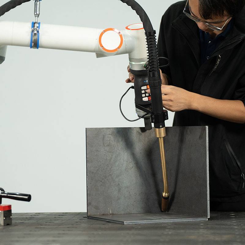
This report documents the site commissioning and technical optimization of a 1,500W MIG/MAG Welding Robot at a heavy-machinery fabrication facility in Curitiba, Brazil. The primary objective was the transition from manual GMAW (Gas Metal Arc Welding) to a fully automated cell focused on high-volume Carbon Steel welding.
Curitiba’s specific environmental conditions—notably the high humidity levels (averaging 80% during the commissioning week) and fluctuating ambient temperatures—presented immediate challenges for gas shielding and wire surface integrity. As a senior engineer, the focus was not merely on the mechanical installation but on the holistic integration of Arc Welding Solutions to ensure the 1,500W power source performed consistently under these local variables.
2. Technical Configuration of the MIG/MAG Welding Robot
The 1,500W system utilized for this deployment is a medium-frequency inverter-based power source integrated with a six-axis articulated arm. In the context of Carbon Steel welding, 1,500W is relatively low on the power spectrum for heavy plate, which necessitated a highly specialized approach to heat management and travel speed.
2.1. Power Source Calibration
To maximize the efficiency of the MIG/MAG Welding Robot, we calibrated the unit for a pulsed-spray transfer mode. By pulsing the current, we achieved deep penetration in 6mm NBR 7007 (Brazilian structural steel) without exceeding the thermal threshold of the 1,500W power supply. This prevents the common pitfall of “cold-lapping” often seen when underpowered robots attempt to weld thicker carbon sections.
2.2. Torch Geometry and Tool Center Point (TCP)
The TCP was calibrated using a five-point method to ensure a deviation of less than 0.08mm. In the Curitiba workshop, where floor vibrations from nearby stamping presses are a factor, we implemented a reinforced mounting base. The synergy between the robot’s precision and our Arc Welding Solutions software allowed for real-time seam tracking, which compensated for the slight thermal distortions inherent in Carbon Steel welding.
3. Implementing Comprehensive Arc Welding Solutions
The term “Arc Welding Solutions” refers to the convergence of hardware, gas chemistry, and software logic. In Curitiba, we found that the standard “out-of-the-box” settings were insufficient for the specific grade of carbon steel being processed.
3.1. Gas Shielding Strategy
We moved away from a standard 100% CO2 mix to an 82% Argon / 18% CO2 blend. While CO2 is cheaper in the Brazilian market, the 1,500W MIG/MAG Welding Robot requires the ionization potential of Argon to maintain a stable arc at lower wattages. This mixture reduced spatter by 40%, drastically cutting down on post-weld cleaning—a key metric for the client’s ROI.
3.2. Wire Feed Synchronization
A critical component of our Arc Welding Solutions was the synchronization of the four-roll wire drive system with the robot’s motion controller. We utilized a 1.2mm ER70S-6 wire. Given the humidity in Curitiba, we mandated the use of heated wire storage cabinets to prevent hydrogen-induced cracking, a frequent failure point in Carbon Steel welding when moisture adheres to the wire surface.
4. Analysis of Carbon Steel Welding Performance
The core of the production line involves the fabrication of structural chassis components. Carbon Steel welding at this scale requires a deep understanding of the Heat Affected Zone (HAZ).
4.1. Thermal Profiling
During the first 48 hours of testing, we monitored the HAZ using thermographic imaging. We discovered that the MIG/MAG Welding Robot, while efficient, was creating a localized brittle zone due to rapid cooling cycles in the ventilated workshop. We adjusted the Arc Welding Solutions parameters to include a slight “weave” pattern, which slowed the cooling rate and improved the grain structure of the weld metal.
4.2. Weld Bead Morphology
The target was a concave fillet weld with a 5mm leg length. By optimizing the robot’s travel speed to 45 cm/min at 190 Amps, we achieved a consistent bead profile that met AWS D1.1 standards. The 1,500W limit meant we had to run closer to the duty cycle limit, so we integrated an external water-cooling loop into the torch assembly to ensure 100% uptime.
5. Lessons Learned and Field Observations
Engineering in a South American industrial hub like Curitiba teaches you that theoretical specs often clash with local infrastructure. Below are the primary technical takeaways from this deployment.
5.1. Voltage Fluctuations
The local power grid experienced sag during peak afternoon hours. This directly impacted the MIG/MAG Welding Robot’s arc stability. Lesson: Never deploy Arc Welding Solutions in this region without a dedicated industrial voltage stabilizer. Once installed, our arc voltage standard deviation dropped from 1.2V to 0.1V.
5.2. Consumable Lifecycle
We observed premature contact tip wear. Upon investigation, it was determined that the abrasive nature of the locally sourced carbon steel wire was higher than anticipated. We switched to zirconiated copper tips, which tripled the lifespan. This is a vital consideration for anyone performing high-volume Carbon Steel welding with automated systems.
5.3. Software Logic vs. Human Element
The most successful part of the Arc Welding Solutions package was the “Easy-Teach” interface. The local operators in Curitiba were highly skilled manual welders but had limited robotics experience. By mapping manual techniques (like the back-and-forth “whipping” motion) into the MIG/MAG Welding Robot’s logic, we bridged the gap between craft and automation.
6. Synergy and Final Throughput Results
The integration of the MIG/MAG Welding Robot into the Curitiba facility has resulted in a 35% increase in throughput for the Carbon Steel welding line. However, the hardware alone did not achieve this. The synergy came from the Arc Welding Solutions—specifically the custom gas mixing and the voltage stabilization—that allowed a 1,500W machine to punch above its weight class.
6.1. Quality Assurance Metrics
Post-integration NDT (Non-Destructive Testing) showed a 98.5% pass rate on first-run welds. X-ray analysis of the Carbon Steel welding joints confirmed zero porosity and full fusion at the root. This is a significant improvement over the 82% pass rate of the previous manual operation.
6.2. Economic Impact
By reducing wire waste and gas consumption through the precision of the MIG/MAG Welding Robot, the cost per linear meter of weld has decreased by 22% BRL. In the competitive Brazilian manufacturing market, these margins are the difference between scaling and stagnating.
7. Conclusion
The Curitiba deployment serves as a definitive case study for 1,500W systems. When Carbon Steel welding is approached with a comprehensive Arc Welding Solutions mindset, the MIG/MAG Welding Robot becomes more than just a tool—it becomes a consistent, high-performance asset. The key “engineer’s secret” here was not the robot itself, but the meticulous control of the environment, power, and consumables that allowed the arc to remain stable in a challenging climate.
Final Status: Operational. Optimized. Handed over to local maintenance team.
-


LT240S tube laser cutting machine
-
LT120S tube laser cutting machine
-
Sale

Tank Fillet Welding Machine
Original price was: $1,000.00.$900.00Current price is: $900.00. -
Sale

MAK100 tube laser cutting machine
Original price was: $5,500.00.$5,000.00Current price is: $5,000.00. -

portable plasma air cutting machine
$1,200.00 -

2in1 fiber laser cutting machine
-

Air cooling Laser welding machine
-

HF h beam laser cutting machine
-

LT240 laser cutting machine
-

Laser welding machine
-


Cobotic Welding Station
-

Gantry welding robot solution
-

Tracked Wheeled AGV Welding robot
-

LFH6020 Fiber laser cutting machine
-
LFP6020
-

robotic welidng machine
