Automatic Girth Seam Welder with Laser Seam Tracking for Oil & Gas Tanks
In this article
Technical Optimization of Tank Shell Fabrication
The construction of field-erected storage tanks, specifically those adhering to API 650 or API 620 standards, requires high-integrity horizontal girth seams. Historically, these seams were executed via manual shielded metal arc welding (SMAW) or semi-automatic methods, both of which are susceptible to operator fatigue and inconsistent penetration. The modern Automatic Girth Welder (AGW) represents a paradigm shift in industrial engineering, providing a mobile, robotic platform that straddles the tank shell to deliver continuous, high-quality welds. By integrating robotic control units with Metal Active Gas (MAG) processes, manufacturers can achieve duty cycles that exceed 80%, compared to the 30-40% typically seen in manual operations.
Robotic MAG Welding Dynamics
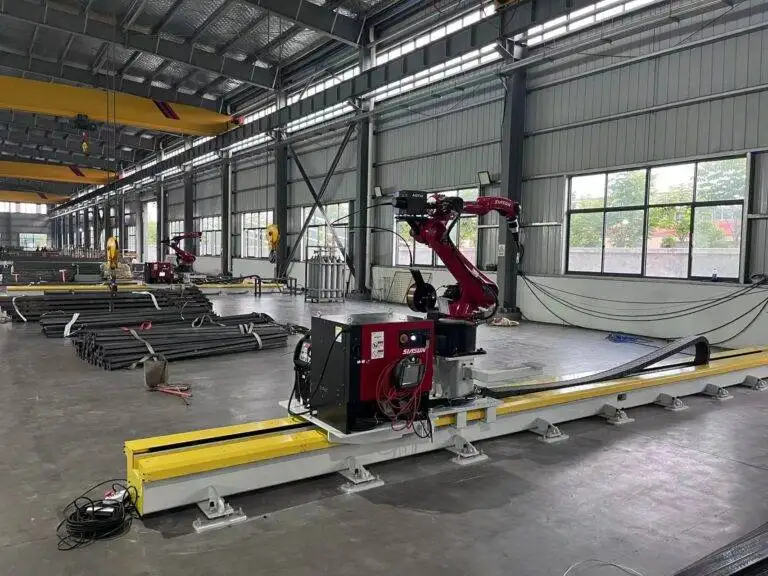
The core of the automated system is the Robotic Welding head configured for Metal Active Gas (MAG) welding. Unlike submerged arc welding (SAW), which is often used in shop environments, MAG welding in the field offers greater visibility and faster setup times for the girth seam. The robotic system controls the wire feed speed, voltage, and travel speed with millisecond precision. In the context of oil and gas tanks, where steel thickness can vary significantly from the bottom course to the top course, the ability of the robot to adjust parameters on the fly is essential.
Robotic MAG systems utilized in AGW units typically employ a pulsed spray transfer mode. This mode allows for high deposition rates while maintaining a stable arc and minimizing spatter. The reduction in spatter is not merely aesthetic; it reduces post-weld cleaning time and prevents surface contaminants that could compromise the tank’s internal coating or external insulation. From an engineering standpoint, the mechanical consistency of the robot ensures that the heat-affected zone (HAZ) is minimized, preserving the metallurgical properties of the high-tensile steel plates used in modern tank designs.

Precision Through Laser Seam Tracking
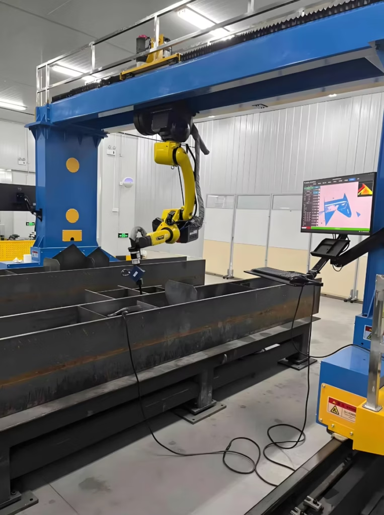
One of the primary challenges in field welding is the irregularity of the plate fit-up. While workshop conditions are controlled, field environments involve wind, uneven foundations, and slight variations in plate curvature. This is where Laser Seam Tracking becomes the critical “nerve system” of the robotic welder. The laser sensor, mounted ahead of the welding torch, scans the groove geometry in real-time. It measures parameters such as the root gap, bevel angle, and plate misalignment (hi-lo).
The data from the laser sensor is processed by the robotic controller, which then calculates the necessary offsets for the torch position. If the plate gap widens, the system can automatically adjust the oscillation width or slow the travel speed to ensure full penetration. This level of adaptive control eliminates the “missed seams” and “lack of fusion” defects common in fixed-speed automated systems. By maintaining the arc precisely in the center of the joint, the system ensures that the weld bead profile meets the stringent radiographic testing (RT) and ultrasonic testing (UT) requirements of the oil and gas industry.
Maintenance Strategies for Peak Operational Availability
To ensure a high mean time between failures (MTBF), a rigorous maintenance schedule is required for the AGW unit. Industrial engineers must focus on the mechanical and electrical subsystems. The drive motors and carriage wheels, which support the entire weight of the operator and the welding equipment, are subject to wear from grit and metallic dust. Regular calibration of the encoder wheels is necessary to ensure that travel speed remains accurate, as even a 5% deviation can lead to over-welding or insufficient throat thickness.
The welding torch and wire delivery system require daily inspections. The contact tips, gas nozzles, and wire liners are consumable items that directly impact arc stability. In a robotic MAG setup, a worn contact tip can cause “micro-arcing,” leading to wire burn-back and system downtime. Furthermore, the laser sensor optics must be kept clean using compressed air or specialized lens wipes to prevent signal degradation. Implementing a predictive maintenance approach—tracking the hours of arc-on time to trigger consumable replacement—maximizes the machine’s availability during the critical path of the construction schedule.
Labor Economics and Return on Investment
The transition to robotic welding is primarily driven by the Return on Investment (ROI) calculated through labor displacement and productivity gains. In a traditional manual welding setup, a large-diameter tank might require a dozen highly skilled welders working simultaneously to meet a deadline. Finding and certifying such a workforce is increasingly difficult and expensive in the current labor market. An AGW unit, operated by a single technician, can replace the output of five to eight manual welders.
The ROI calculation involves several variables:
- Reduction in Man-Hours: Automated systems move at speeds of 500mm to 1000mm per minute, significantly faster than manual hand-over-hand welding.
- Consumable Efficiency: Robotic MAG systems reduce wire waste and shielding gas loss by optimizing the delivery based on the actual weld path.
- Rework Mitigation: Manual welding often sees a 3-5% repair rate on girth seams. Robotic systems with laser tracking typically bring this below 1%, saving thousands of dollars in grinding, re-welding, and re-testing costs.
When factoring in the mobilization costs, the initial capital expenditure (CAPEX) for a robotic AGW unit is often recouped within the first two to three major tank projects. For industrial contractors, the ability to guarantee a project completion date due to the predictable speed of robotic welding provides a competitive advantage that often outweighs the initial purchase price.
Integrating Data for Process Improvement
Modern robotic girth welders are increasingly equipped with data logging capabilities. Every weld pass can be recorded, providing a digital twin of the tank’s construction. This data includes the exact amperage, voltage, and travel speed for every centimeter of the girth seam. For oil and gas operators, this documentation is invaluable for long-term asset integrity management. If a failure occurs decades later, the historical data can help engineers determine if the welding parameters contributed to the issue.
From a process improvement perspective, analyzing this data allows industrial engineers to identify bottlenecks. If the laser tracking system frequently slows down in a particular section, it may indicate a systemic issue with the plate rolling or fit-up process earlier in the production line. This feedback loop allows for continuous optimization of the entire tank farm construction workflow, moving beyond the welding torch to the very beginning of the fabrication cycle.
Conclusion
The integration of robotic MAG welding and laser tracking into Automatic Girth Welders represents the peak of current tank fabrication technology. By focusing on mechanical precision, rigorous maintenance, and the clear economic benefits of automation, industrial firms can significantly enhance their throughput. In an industry where safety and structural integrity are non-negotiable, the shift toward robotic systems provides the consistency and reliability required for the next generation of energy storage infrastructure.