Engineering Review: Multi-pass Welding Automated MAG Welding Cell – Bengaluru, India
In this article
- Field Report: Deployment of Automated MAG Welding Cell for Multi-pass Infrastructure Components
- 1. Project Overview and Site Context
- 2. The Synergy: Automated MAG Welding Cell and Arc Welding Solutions
- 3. Technical Challenges in Galvanized Pipe Welding
- 4. Multi-pass Strategy and Parameter Logic
- 5. Site-Specific Lessons Learned in Bengaluru
- 6. Quality Assurance and NDT Results
- 7. Conclusion: The Value Proposition
Field Report: Deployment of Automated MAG Welding Cell for Multi-pass Infrastructure Components
1. Project Overview and Site Context
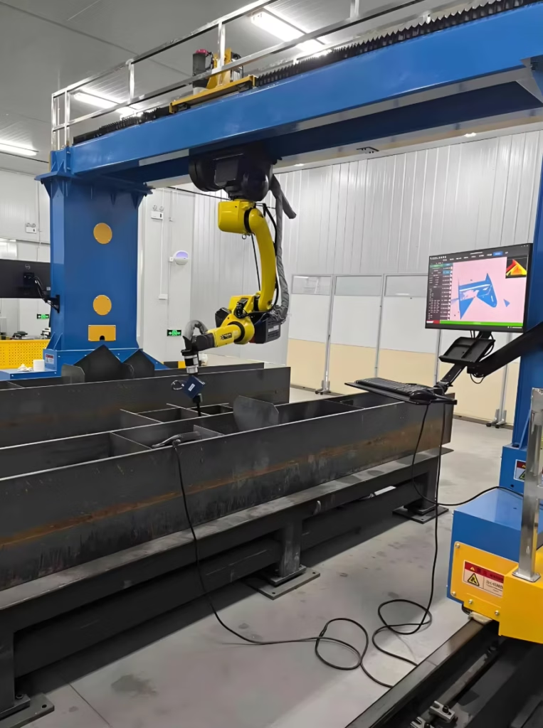
This report summarizes the commissioning and optimization of a high-duty cycle Automated MAG Welding Cell at a heavy-engineering facility in Bengaluru, India. The primary objective was to transition from manual stick welding to an integrated robotic system capable of handling thick-walled Galvanized Pipe welding for large-scale municipal water infrastructure.
The Bengaluru workshop environment presents specific challenges: high ambient humidity during monsoon periods and localized voltage fluctuations. These variables necessitated a robust suite of Arc Welding Solutions that could maintain arc stability without constant operator intervention. The transition to automation was not merely a speed upgrade but a metallurgical requirement to ensure consistent fusion in multi-pass configurations where manual inconsistency previously led to high repair rates.
2. The Synergy: Automated MAG Welding Cell and Arc Welding Solutions
The core of this deployment is the integration between the 6-axis robotic arm and the digital power source—a synergy we define as the “Solution” rather than just “Hardware.” An Automated MAG Welding Cell is only as effective as the software logic governing it. In this Bengaluru installation, we utilized a “Twin-Pulse” Arc Welding Solution to manage the heat input during the root pass of the pipes.
The synergy works by linking the robot’s travel speed directly to the power source’s adaptive arc control. When the sensors detect a slight variation in the pipe’s bevel—common in large-diameter Galvanized Pipe welding—the Arc Welding Solutions software adjusts the wire feed speed and voltage in real-time (within milliseconds). This prevents the “burn-through” or “cold lap” issues that typically plague automated systems when dealing with the inconsistent tolerances of heavy-walled piping.
3. Technical Challenges in Galvanized Pipe Welding
The primary technical hurdle encountered was the vapor pressure of zinc. Zinc boils at approximately 907°C, while steel melts at roughly 1,500°C. During the MAG (Metal Active Gas) process, the zinc coating ahead of the weld pool vaporizes instantly, often becoming trapped in the solidifying weld metal, leading to severe porosity and “wormholes.”
3.1 Pre-Weld Preparation Protocols
We implemented a strict mechanical removal protocol. Despite the “automated” nature of the cell, the Galvanized Pipe welding process requires the removal of the zinc layer at least 20mm from the weld land. We found that even trace amounts of zinc led to spatter that fouled the gas nozzle of the Automated MAG Welding Cell, necessitating more frequent cleaning cycles and reducing the “Arc-on” time.
3.2 Shielding Gas Selection
Traditional 80/20 Argon/CO2 mixes were found insufficient for the galvanized layers. We shifted to a 90/10 mix with a higher flow rate (22 L/min) to provide a more “forceful” gas shield that helps push the zinc vapors out of the weld zone. This adjustment is a critical component of our site-specific Arc Welding Solutions, tailored to the atmospheric conditions of the Bengaluru facility.
4. Multi-pass Strategy and Parameter Logic
The project involved 12mm wall thickness pipes, requiring a three-pass sequence: Root, Fill, and Cap. Each pass required a distinct program within the Automated MAG Welding Cell.
4.1 The Root Pass (Short-Circuit Transfer)
For the root, we used a modified short-circuit process. The goal was to achieve full penetration without a backing bar. The Arc Welding Solutions software provided a “surface tension transfer” equivalent, which allowed the weld pool to bridge the gap (3mm) even with slight fit-up variations.
- Current: 140-160A
- Voltage: 17-19V
- Travel Speed: 25 cm/min
4.2 The Fill Pass (Pulsed Spray Transfer)
The fill pass utilized a pulsed spray transfer to maximize deposition rates while keeping the heat-affected zone (HAZ) narrow. This is where the Automated MAG Welding Cell truly outpaces manual labor. We maintained a high deposition rate of 4.5 kg/hr.
- Current: 240-260A
- Voltage: 26-28V (Pulsed)
- Oscillation: 3mm width, 2Hz frequency
4.3 The Cap Pass (Stringer Bead)
To ensure aesthetic quality and minimize post-weld cleaning, the cap pass was executed as a series of stringer beads rather than a wide weave. This reduces the risk of undercut at the edges of the Galvanized Pipe welding zone, where the protective coating has been removed.
5. Site-Specific Lessons Learned in Bengaluru
Operating a high-end Automated MAG Welding Cell in the Bengaluru industrial corridor provided several “on-the-ground” insights that aren’t found in the manual.
5.1 Power Conditioning
We observed frequent “micro-trips” in the local grid. While the robot’s controllers have some tolerance, the Arc Welding Solutions were sensitive to voltage drops, causing the arc to extinguish mid-pass. Lesson: We installed a dedicated industrial UPS for the control logic and a heavy-duty stabilizer for the power source. Since this installation, “re-start” defects have dropped by 90%.
5.2 Wire Feeding Consistency
The humidity in Bengaluru can lead to oxidation on the surface of the ER70S-6 welding wire if left in the cell overnight. This oxidation increases friction in the liners, leading to “bird-nesting” in the Automated MAG Welding Cell drive rolls. Lesson: We mandated the use of plastic-enclosed wire drums with desiccant packs and replaced standard liners with low-friction Teflon-carbon liners.
5.3 Fume Extraction for Zinc
When Galvanized Pipe welding is moved into an automated environment, the volume of zinc oxide fumes increases exponentially due to the higher duty cycle. The existing workshop ventilation was inadequate. We integrated a high-vacuum, “at-the-torch” extraction system. This not only protected the operators but also prevented the accumulation of white zinc dust on the robotic arm’s optical sensors.
6. Quality Assurance and NDT Results
Post-commissioning, 50 joints were subjected to Radiographic Testing (RT) and Ultrasonic Testing (UT).
- Success Rate: 48/50 joints passed on the first attempt.
- Failure Mode: Two joints showed “lack of sidewall fusion” in the fill pass. Investigation revealed an incorrect torch angle during the 2 o’clock position of the pipe rotation.
- Correction: We recalibrated the Automated MAG Welding Cell pathing to include a more aggressive torch lead angle (15 degrees) to ensure the arc force was directed into the bevel face.
7. Conclusion: The Value Proposition
The deployment of the Automated MAG Welding Cell in this Bengaluru facility has demonstrated that high-tech Arc Welding Solutions can be successfully adapted to “dirty” materials like galvanized steel. The key is not to treat the robot as a ‘set-and-forget’ tool, but as a platform for precise metallurgical control.
For future Galvanized Pipe welding projects, the focus should remain on the “Three Pillars”: aggressive pre-weld cleaning, specific gas chemistry, and adaptive power parameters. By addressing the localized environmental challenges of the Bengaluru site—specifically power stability and humidity—we have achieved a system that produces X-ray quality welds at three times the speed of the previous manual process. The project is cleared for full-scale production.
Signed,
Senior Welding Engineer
Field Operations – Bengaluru Division