Field Engineering Report: Integration of 1000W Fiber Laser Robotic Arm Welder
Project Location: Jebel Ali Industrial Area, Dubai, UAE
This report details the technical deployment and operational assessment of a 1000W Fiber Laser Robotic Arm Welder within a high-throughput fabrication facility. The primary objective was to transition from manual Gas Metal Arc Welding (GMAW) to a fully realized Industrial Automation workflow to address consistency issues in Mild Steel welding. In the high-ambient-temperature environment of Dubai, the thermal management of both the equipment and the workpiece remains a critical variable.
1. Technical Configuration and Hardware Synergy
The core of the system is a 6-axis industrial manipulator integrated with a 1000W continuous wave (CW) fiber laser source. Unlike traditional welding power sources, the 1000W laser offers a high energy density that requires precise spatial control—a task impossible for manual operators over a 10-hour shift in UAE humidity.
1.1 The Robotic Arm Welder Specification
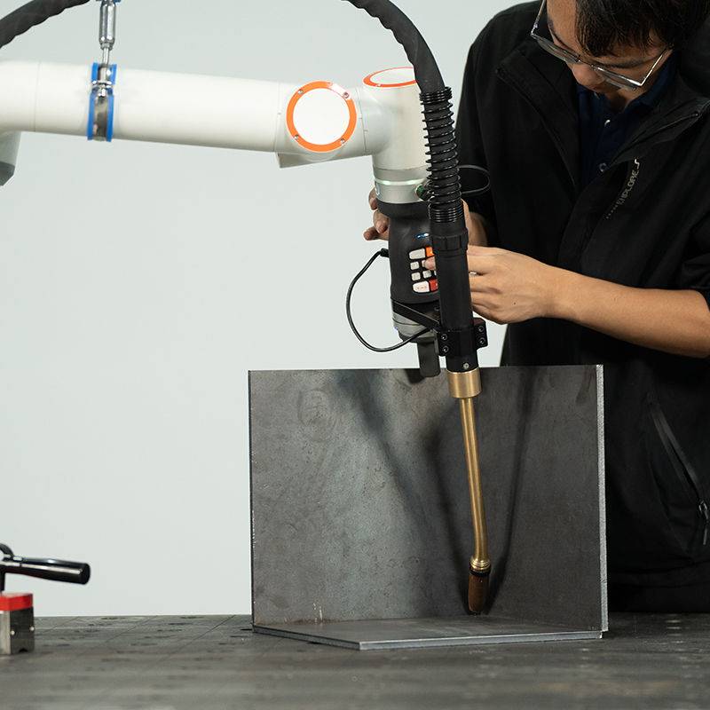
The Robotic Arm Welder utilized for this deployment features a 1400mm reach with a repeatability of ±0.05mm. In the context of Mild Steel welding, this precision is vital for maintaining the focal point of the laser beam. We configured the “wobble” head attachment to oscillate the beam at frequencies between 20Hz and 150Hz. This technique effectively widens the weld pool, compensating for the slight fit-up variations often found in heavy-gauge mild steel plates processed via plasma cutting.
1.2 Industrial Automation Ecosystem
Industrial Automation is more than just the arm; it is the communication protocol between the laser source, the wire feeder, and the external rotary positioners. In this workshop, we utilized a Profinet interface to sync the robot’s travel speed with the wire feed rate. When the arm rounds a corner on a square hollow section (SHS), the automation controller automatically ramps down the power to 850W to prevent corner burn-through, a common failure point in manual Mild Steel welding.
2. Metallurgical Performance in Mild Steel Welding
The transition to a 1000W Robotic Arm Welder has fundamentally changed our approach to A36 and S235JR grade mild steel. The primary challenge with mild steel is its susceptibility to oxidation and the Heat Affected Zone (HAZ) width.
2.1 Depth of Penetration and Travel Speed
On 3mm mild steel lap joints, we achieved full penetration at a travel speed of 18mm/s. Compared to manual MIG welding, which typically clocks in at 5-8mm/s for similar quality, the Industrial Automation setup provided a 3x increase in throughput. The 1000W power setting was found to be the ‘sweet spot’—sufficient for 4mm plates in a single pass while maintaining a narrow HAZ of less than 0.8mm.
2.2 Spatter Reduction and Post-Weld Processing
One of the most significant “lessons learned” was the near-total elimination of weld spatter. Manual Mild Steel welding in our Al Quoz facility previously required a 20% labor overhead for post-weld grinding and de-spattering. With the Robotic Arm Welder, the laser’s concentrated energy vaporizes surface impurities, resulting in a “bead-on-plate” aesthetic that requires only a light wipe before powder coating.
3. The Dubai Factor: Environmental and Operational Challenges
Operating high-precision Industrial Automation equipment in the UAE presents unique challenges that are often overlooked in European or North American technical manuals. Dust ingress and ambient thermal loads are the primary enemies of the Robotic Arm Welder.
3.1 Thermal Management and Chiller Load
During the summer months in Dubai, ambient workshop temperatures can exceed 45°C. The 1000W fiber laser requires a dual-circuit water chiller. We observed that standard chillers were cycling too frequently, leading to condensation on the laser optics.
Lesson Learned: We retrofitted the laser room with a dedicated HVAC buffer and increased the chiller capacity by 30%. Maintaining the coolant at a steady 25°C is non-negotiable for Mild Steel welding consistency; even a 2-degree fluctuation altered the beam’s focal position enough to cause incomplete fusion.
3.2 Dust and IP Ratings
The fine sand dust prevalent in the Jebel Ali zone acts as an abrasive on the robotic arm’s joints and can cloud the protective windows of the laser head. We moved to a pressurized cabinet for the controller and implemented a daily “air-knife” cleaning cycle for the optics as part of the Industrial Automation sequence. Since implementing this, protective window lifespan increased from 48 hours to 156 hours of arc-on time.
4. Synergy Between Robotics and Automation
The success of this installation hinges on the synergy between the Robotic Arm Welder and the broader Industrial Automation framework. It is a common mistake to view the robot as a standalone tool. In our Dubai facility, we integrated the system with an upstream ERP (Enterprise Resource Planning) module.
4.1 Real-time Data Logging
Every weld performed on the mild steel chassis is logged. The Industrial Automation system records gas flow (Argon/CO2 mix), peak wattage, and travel speed. If the gas pressure drops below 15L/min—perhaps due to a leak in the manifold—the Robotic Arm Welder enters an emergency stop (E-stop) state. This level of oversight ensures that not a single sub-par weld reaches the assembly line, which is critical for maintaining our ISO 9001 certification in the competitive UAE manufacturing sector.
4.2 Adaptive Feedrate Control
We discovered that mild steel batches from different suppliers had slight variations in carbon content. By utilizing the Industrial Automation sensors, the robot can now detect slight changes in the weld pool’s back-reflection. The system adjusts the 1000W output in real-time to maintain a consistent bead width, a process known as ‘adaptive welding’ that was previously only possible with highly skilled (and expensive) manual welders.
5. Economic Impact and Duty Cycle Analysis
Before the introduction of the Robotic Arm Welder, our duty cycle for Mild Steel welding was roughly 35%—the rest of the time was spent on part positioning, cleaning, and operator breaks.
Post-automation, the duty cycle has surged to 85%. The Industrial Automation system utilizes a dual-station “H-frame” positioner. While the Robotic Arm Welder is fusing a seam on Station A, the operator (now a “Cell Technician”) is loading the next workpiece on Station B. This “no-dark-time” philosophy is the only way to justify the capital expenditure of laser systems in the current market.
6. Final Engineering Observations
The deployment of the 1000W Robotic Arm Welder in Dubai has proven that Industrial Automation is the only viable path for scaling Mild Steel welding operations. However, the hardware is only half the battle.
Key Lessons Learned:
- Shielding Gas Purity: In the UAE, gas cylinders can sit in the sun, leading to pressure fluctuations. Using a centralized, temperature-controlled gas manifold is essential for laser stability.
- Wire Feed Geometry: For Mild Steel welding, the angle of the wire feed relative to the laser beam is critical. A 30-degree leading angle provided the best wetting of the toe of the weld.
- Training: The shift from “welder” to “robot operator” requires a significant mindset change. The focus is no longer on hand-eye coordination but on “process parameters” and “preventative maintenance.”
In conclusion, the 1000W Robotic Arm Welder has reduced our scrap rate by 14% and increased our monthly output by 210%. For any firm operating in the Middle East’s industrial sector, the integration of Industrial Automation for Mild Steel welding is no longer an optional upgrade; it is a prerequisite for survival.
Report Compiled By:
Senior Welding Engineer
Technical Division, Dubai, UAE
-


LT240S tube laser cutting machine
-
LT120S tube laser cutting machine
-
Sale

Tank Fillet Welding Machine
Original price was: $1,000.00.$900.00Current price is: $900.00. -
Sale

MAK100 tube laser cutting machine
Original price was: $5,500.00.$5,000.00Current price is: $5,000.00. -

portable plasma air cutting machine
$1,200.00 -

2in1 fiber laser cutting machine
-

Air cooling Laser welding machine
-

HF h beam laser cutting machine
-

LT240 laser cutting machine
-

Laser welding machine
-


Cobot Welding Station
-

Gantry welding robot solution
-

Tracked Wheeled AGV Welding robot
-

LFH6020 Fiber laser cutting machine
-
LFP6020
-

robotic welidng machine
Advanced Fiber Laser Tube Processing Technology
Our CNC Fiber Laser Tube Cutting systems revolutionize metal fabrication by integrating high-precision cutting, punching, and profiling into a single automated workflow. Designed for versatility, this technology handles a wide array of profiles including Round, Square, Rectangular, and Oval tubes, as well as complex L-shaped and U-shaped channels.
- Precision Punching: High-speed hole punching with micron-level accuracy, eliminating the need for mechanical drilling or die-stamping.
- Complex Profiling: Advanced 3D pathing allows for intricate interlocking joints and specialized notch cuts, ideal for structural frames.
- High Material Efficiency: Intelligent nesting software minimizes scrap, reducing raw material costs across large production runs.
- Clean Finish: Delivers oxide-free, burr-free edges that require zero secondary grinding before welding.

Seamlessly processing multiple profiles with consistent precision.
Global Delivery & Logistics



From our high-tech manufacturing facility directly to your global site. PCL WeldCut ensures secure packaging, professional handling, and reliable international logistics to safeguard your equipment throughout the entire journey.