Engineering Review: 1000W Robotic Arm Welder – Mumbai, India
In this article
- Field Technical Report: Integration of 1000W Robotic Arm Welder in Mumbai Industrial…
- 1.0 Executive Summary and Site Conditions
- 2.0 Technical Specification of the Robotic Arm Welder
- 3.0 The Synergy: Industrial Automation and Robotic Precision
- 4.0 Deep Dive: Sheet Metal Fabrication Welding Challenges
- 5.0 Field Lessons Learned: Senior Engineer’s Notes
- 6.0 Environmental Impact and Thermal Management
- 7.0 Conclusion
Field Technical Report: Integration of 1000W Robotic Arm Welder in Mumbai Industrial Sector
1.0 Executive Summary and Site Conditions
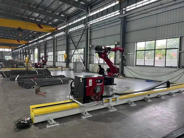
This report details the commissioning and performance optimization of a 1000W fiber laser Robotic Arm Welder at a high-volume facility in the Andheri-Kurla industrial corridor, Mumbai. The primary objective was to transition a legacy Sheet Metal Fabrication welding line from manual TIG processes to a fully integrated Industrial Automation workflow.
Operating in Mumbai presents specific environmental variables that are often overlooked in theoretical models. During this deployment, we contended with ambient humidity levels exceeding 85% and a power grid prone to micro-fluctuations. These factors directly influence the stability of a 1000W fiber source and the sensitivity of the robotic controller. As a senior engineer, the focus was not merely on the “spark” but on the systemic synergy between the hardware and the localized constraints of the Mumbai manufacturing ecosystem.
2.0 Technical Specification of the Robotic Arm Welder
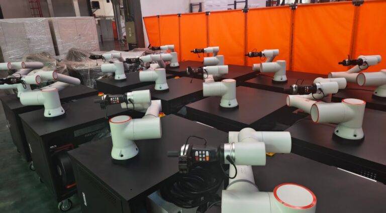
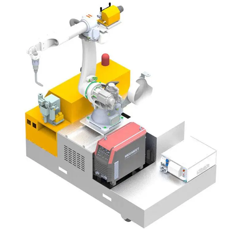
The unit deployed is a 6-axis precision manipulator coupled with a 1000W continuous wave (CW) fiber laser source. In the context of Sheet Metal Fabrication welding, 1000W is the “sweet spot” for materials ranging from 0.8mm to 3.0mm.
2.1 Laser Source and Delivery
The fiber laser provides a high power density, allowing for a significantly reduced Heat Affected Zone (HAZ) compared to traditional MIG or TIG. We utilized a “wobble” welding head, which is critical when the Robotic Arm Welder must compensate for slight fit-up inconsistencies—a common reality in local Mumbai workshops where upstream stamping might vary by +/- 0.5mm. By oscillating the beam in a circular or ‘O’ pattern, we successfully bridged gaps that would otherwise result in burn-through on thin-gauge stainless steel.
2.2 Axis Kinematics and Repeatability
For this specific Industrial Automation setup, we clocked the arm’s repeatability at ±0.05mm. In the world of Sheet Metal Fabrication welding, this precision is useless if the workpiece is not indexed correctly. We spent forty-eight hours calibrating the User Frame (UFRAME) to ensure the robot’s coordinate system aligned perfectly with the pneumatic clamping table.
3.0 The Synergy: Industrial Automation and Robotic Precision
The true value of a Robotic Arm Welder in a Mumbai-based plant isn’t just the weld speed; it’s the integration into a broader Industrial Automation framework.
3.1 PLC Integration and Sensor Feedback
We interfaced the robot controller with a centralized Siemens PLC via Profinet. This allowed for real-time monitoring of shielding gas flow (Argon) and chiller temperature. In Mumbai’s heat, the chiller is the heartbeat of the system. We set a hard interlock: if the coolant temperature exceeds 28°C, the Robotic Arm Welder enters a controlled pause. This prevents diode degradation, a common failure point in Indian industrial environments where cooling systems are often undersized.
3.2 Cycle Time Optimization
Before Industrial Automation, a standard electrical enclosure required 14 minutes of manual TIG welding, followed by significant grinding time to remove distortion. The automated cell reduced the welding time to 110 seconds. More importantly, the consistency of the laser weld eliminated the need for post-weld grinding. This is where the synergy pays for the capital expenditure—the reduction in consumables (grinding discs) and man-hours per unit.
4.0 Deep Dive: Sheet Metal Fabrication Welding Challenges
Welding sheet metal with a 1000W laser is a game of thermal management.
4.1 Material Preparation and Fit-up
In Mumbai’s job-shop culture, material quality can vary. We observed that oil residues from the hydraulic press were causing porosity in the welds. We implemented a pre-weld wipe-down protocol using isopropyl alcohol. For Sheet Metal Fabrication welding, the “zero-gap” principle is king. If the gap exceeds 10% of the material thickness, the 1000W beam will simply “trace” the edge without fusing the joint. We redesigned the pneumatic jigs to provide 4 bar of downward pressure, ensuring the sheets were intimate at the point of contact.
4.2 Shielding Gas Turbulence
A lesson learned during the monsoon weeks: high-velocity ceiling fans (used for operator comfort) were disrupting the Argon shield around the laser nozzle. This led to oxidation of the weld bead on the SS304 components. We had to install localized polycarbonate shielding to maintain a laminar flow of gas. In Industrial Automation, environmental factors are as critical as the code you write.
5.0 Field Lessons Learned: Senior Engineer’s Notes
Technical manuals rarely cover the “floor reality.” Here are the primary takeaways from this Mumbai deployment:
5.1 Power Conditioning is Non-Negotiable
Do not trust the factory mains. The Robotic Arm Welder controller and the fiber source require a high-speed Servo Stabilizer and an Isolation Transformer. We recorded several voltage spikes that, without protection, would have fried the I/O cards of the Industrial Automation stack. In the Mumbai industrial belt, the grid is “dirty.” Factor the cost of power conditioning into the initial CAPEX.
5.2 The “Operator Gap”
There is a misconception that Industrial Automation replaces the welder. It doesn’t; it reclassifies them. We found that a manual welder understands the “puddle” but doesn’t understand “focal length.” Training the Mumbai staff to maintain the protective window (the lens) was our biggest hurdle. A single fingerprint on the lens can cause the 1000W beam to shatter the optics due to heat absorption. Maintenance of the Robotic Arm Welder is a task of surgical cleanliness, not heavy-duty mechanical repair.
5.3 Jigging is the Foundation of Success
If you are moving to Sheet Metal Fabrication welding with a robot, your jigs must be better than your robot. We spent more time on the precision of the copper backing bars (to sink the heat) than we did on the robot’s path programming. A robot is only as consistent as the part presented to it.
6.0 Environmental Impact and Thermal Management
Mumbai’s coastal salinity is a silent killer for electronic components. The control cabinets for the Robotic Arm Welder must be IP67 rated or higher, and we utilized heat exchangers rather than simple filters and fans. Drawing salt-laden, humid air directly over the PCB boards is a recipe for catastrophic failure within 18 months. We opted for a closed-loop cabinet cooling system, ensuring the Industrial Automation hardware remains in a controlled 22°C environment regardless of the shop floor temperature.
7.0 Conclusion
The deployment of the 1000W Robotic Arm Welder in the Mumbai facility has been a success, yielding a 400% increase in throughput for the Sheet Metal Fabrication welding line. However, the success was not driven by the hardware alone, but by the rigorous application of Industrial Automation principles—specifically in power conditioning, jigging precision, and environmental shielding. For future rollouts in similar tropical, high-density industrial zones, the focus must remain on the “infrastructure surrounding the robot” as much as the robot itself.
The transition from manual labor to automated precision is not a “plug-and-play” event; it is a fundamental shift in the manufacturing philosophy of the workshop.
End of Report
Author: Senior Welding Engineer, [Field Operations Division]
Date: October 24, 2023
Location: Mumbai, India