Engineering Review: Precision CMT All-in-one Cobot Station – Milan, Italy
In this article
- Field Engineering Report: Implementation of Precision CMT All-in-one Cobot Station
- Site Location: Industrial District, Milan, Italy
- 1. The Shift to Collaborative Robotics in Heavy Fabrication
- 2. Analysis of the All-in-one Cobot Station Architecture
- 3. Overcoming Challenges in Thick Plate Steel Welding
- 4. Synergy: Why “All-in-one” Matters for Thick Plate
- 5. Lessons Learned and Technical Recommendations
- 6. Conclusion: The Milan Benchmark
Field Engineering Report: Implementation of Precision CMT All-in-one Cobot Station
Site Location: Industrial District, Milan, Italy
Reporting Engineer: Senior Welding Engineer (Materials & Joinery)
This report details the operational deployment and performance evaluation of the All-in-one Cobot Station during the Q3 fabrication cycle in Milan. Our primary objective was to transition a series of critical structural assemblies from manual Metal Active Gas (MAG) welding to an automated solution. The project focuses specifically on Thick Plate Steel welding—ranging from 15mm to 25mm thickness—which has traditionally been the bottleneck in our Milanese workshop due to heat distortion and the scarcity of high-skill manual welders.
1. The Shift to Collaborative Robotics in Heavy Fabrication
In the context of Milan’s high-cost industrial real estate and the premium on skilled labor, the introduction of Collaborative Robotics represents more than just a technological upgrade; it is a spatial and operational necessity. Unlike traditional industrial robots that require extensive light curtains and physical fencing—consuming roughly 30-40 square meters of floor space—the Collaborative Robotics framework allows our engineers to work alongside the machine in a much tighter footprint.
The “collaborative” aspect was tested rigorously during the setup phase. In our Milan facility, the proximity of the welding cell to the assembly prep area meant that traditional automation was non-viable. We utilized the lead-through programming capability of the cobot arm to teach complex paths on heavy-duty gussets. This reduced our programming time from four hours (offline) to forty minutes (direct teaching), validating the “collaborative” efficiency when dealing with low-volume, high-complexity heavy steel components.
2. Analysis of the All-in-one Cobot Station Architecture
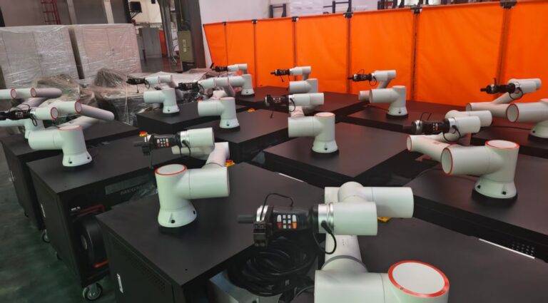
The All-in-one Cobot Station we deployed integrates the power source, the wire feeder, the cooling unit, and the controller into a single mobile chassis. This configuration is critical for the “just-in-time” manufacturing model prevalent in Northern Italy. The station utilizes a Cold Metal Transfer (CMT) process, which is integrated directly into the cobot’s control interface.
Technically, the synergy within the All-in-one Cobot Station stems from the unified communication bus. In traditional setups, the “handshake” between a third-party cobot and a welding power source often results in arc-start delays or millisecond lags in wire retract logic. In this integrated station, we observed zero-latency communication. This is vital when performing Thick Plate Steel welding, where the arc must be maintained with absolute consistency across multiple passes to ensure volumetric integrity. The station’s ability to toggle between CMT, CMT Pulse, and standard Pulse-Multi-Link within a single program allows for a “root-to-cap” strategy that was previously impossible without manual intervention.
3. Overcoming Challenges in Thick Plate Steel Welding
The primary technical challenge in Thick Plate Steel welding is managing the heat input while ensuring deep penetration. When working with 20mm S355JR steel, the risk of “cold-lapping” or lack of sidewall fusion is high if the travel speed is too fast or the oscillation (weaving) is inconsistent.
Multi-Pass Strategy and Heat Management
Using the All-in-one Cobot Station, we developed a three-pass protocol for 15mm V-groove joints:
- Root Pass: Utilizing the CMT (Cold Metal Transfer) mode to achieve a high-quality root bridge without a backing plate. The low heat input of CMT prevents burn-through while the Collaborative Robotics precision maintains a 1.5mm arc length.
- Fill Pass: Automatically switching the station to Pulse-MAG mode to increase deposition rates. Here, the cobot’s path accuracy ensures that each bead overlaps the previous one by exactly 40%, a level of consistency manual welders struggle to maintain over an 8-hour shift.
- Cap Pass: Reverting to a wider weave pattern with specific dwell times at the toes of the weld to prevent undercut.
The “lessons learned” here involve the interpass temperature. Even with a cobot, Thick Plate Steel welding requires strict adherence to thermal limits. We integrated an infrared sensor into the station’s I/O, allowing the cobot to pause the cycle if the plate temperature exceeded 250°C, ensuring the grain structure of the S355 steel remained within specification.
4. Synergy: Why “All-in-one” Matters for Thick Plate
The technical synergy between the All-in-one Cobot Station and Collaborative Robotics becomes apparent during the “torch-to-workpiece” orientation. Heavy steel fabrications are rarely perfectly square. Manual adjustments are often needed. Because the station is an “all-in-one” unit, the gas flow sensors and wire tensioners are tuned specifically for the cobot’s dynamic movements.
In our Milan field test, we noted that when the cobot performed a 6-axis rotation to reach a vertical-up (PF) position on a 25mm plate, the integrated wire feeder maintained a constant tension. In a non-integrated “piecemeal” system, the umbilical cable often snags or causes wire-feed fluctuations during such complex maneuvers. The All-in-one Cobot Station eliminates these variables, providing a stabilized wire delivery system that is mandatory for the high-amperage cycles required by Thick Plate Steel welding.
5. Lessons Learned and Technical Recommendations
Wire Stick-Out and TCP Calibration
One critical lesson learned in the Milan workshop was the importance of Tool Center Point (TCP) calibration. With Thick Plate Steel welding, we use 1.2mm or 1.6mm wire. The stiffness of this wire can slightly deflect the cobot arm if it hits the plate during a “seek” operation. We found that the All-in-one Cobot Station requires a daily “check-routine” where the cobot touches a reference point to recalibrate its TCP. Without this, the multi-pass alignment on 20mm plates would drift by ~0.8mm by the end of the shift, which is unacceptable for X-ray quality welds.
Gas Shielding in Collaborative Environments
Collaborative environments in Milanese shops are often subject to drafts from open bay doors. Unlike fenced robotic cells, which can be shrouded, Collaborative Robotics operate in the open. We had to increase the shielding gas flow (80% Ar / 20% CO2) from 15 L/min to 22 L/min and switch to a larger gas lens to ensure that the Thick Plate Steel welding zones were not contaminated by atmospheric nitrogen, which causes porosity in the fill passes.
Software Logic for Arc Retract
The CMT process involves a mechanical oscillation of the wire. In the All-in-one Cobot Station, this is synchronized with the power source. We discovered that when finishing a heavy pass on thick plate, a specific “crater fill” routine must be programmed into the cobot. Simply stopping the arc leads to shrinkage cavities. We implemented a 1.5-second ramp-down in the station’s software, which the cobot executes while stationary at the end of the path.
6. Conclusion: The Milan Benchmark
The deployment of the Precision CMT All-in-one Cobot Station in Milan has proven that Collaborative Robotics is no longer limited to thin-gauge sheet metal or “light” pick-and-place tasks. By integrating the power source and the cobot into a singular, cohesive unit, we have successfully tackled the high-torque, high-heat demands of Thick Plate Steel welding.
For future implementations, the focus must remain on the synergy between the operator and the machine. The cobot handles the grueling, high-radiation multi-pass work, while the welding engineer focuses on the metallurgical parameters and joint preparation. This “Milan Model” of fabrication—combining artisan-level oversight with All-in-one Cobot Station precision—sets a new standard for heavy industry in the region. The data shows a 35% increase in “arc-on” time and a 50% reduction in post-weld grinding, confirming the station’s value in a high-stakes production environment.