Engineering Review: High-speed MAG Cobot Welder – Chennai, India
In this article
- Field Report: Deployment of High-Speed MAG Cobot Welder in Chennai Industrial Belt
- 1.0 Introduction and Site Conditions
- 2.0 System Architecture: The MAG Cobot Welder
- 3.0 Technical Application: Copper Components Welding
- 4.0 Integration of Arc Welding Solutions
- 5.0 Performance Metrics and Results
- 6.0 Lessons Learned: Engineering Observations
- 7.0 Synergy Evaluation: Cobot vs. Process
- 8.0 Conclusion
Field Report: Deployment of High-Speed MAG Cobot Welder in Chennai Industrial Belt
1.0 Introduction and Site Conditions
This report details the technical implementation and performance evaluation of a high-speed MAG Cobot Welder system at a Tier-1 automotive component manufacturing facility in Sriperumbudur, Chennai. The primary objective was the transition from manual Metal Active Gas (MAG) operations to a collaborative robotic framework to address consistency issues in high-conductivity joints, specifically regarding Copper Components welding used in EV busbar assemblies and heat exchange units.
The environmental factors in Chennai—specifically the high ambient temperature (averaging 38°C) and relative humidity exceeding 75%—presented immediate challenges for the electronic duty cycles of the power sources and the hygroscopic nature of the flux/shielding gas interactions. Our approach focused on integrating a robust suite of Arc Welding Solutions tailored for these specific tropical stressors.
2.0 System Architecture: The MAG Cobot Welder
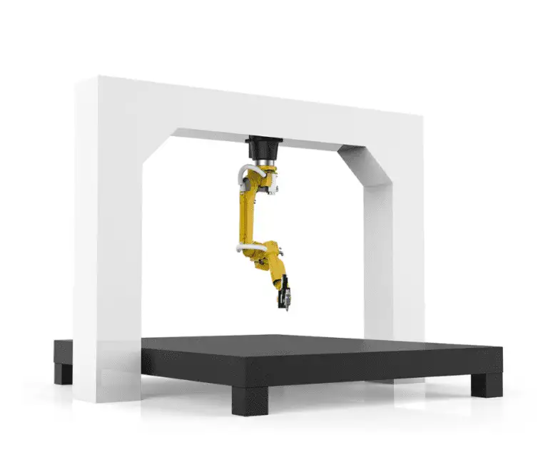
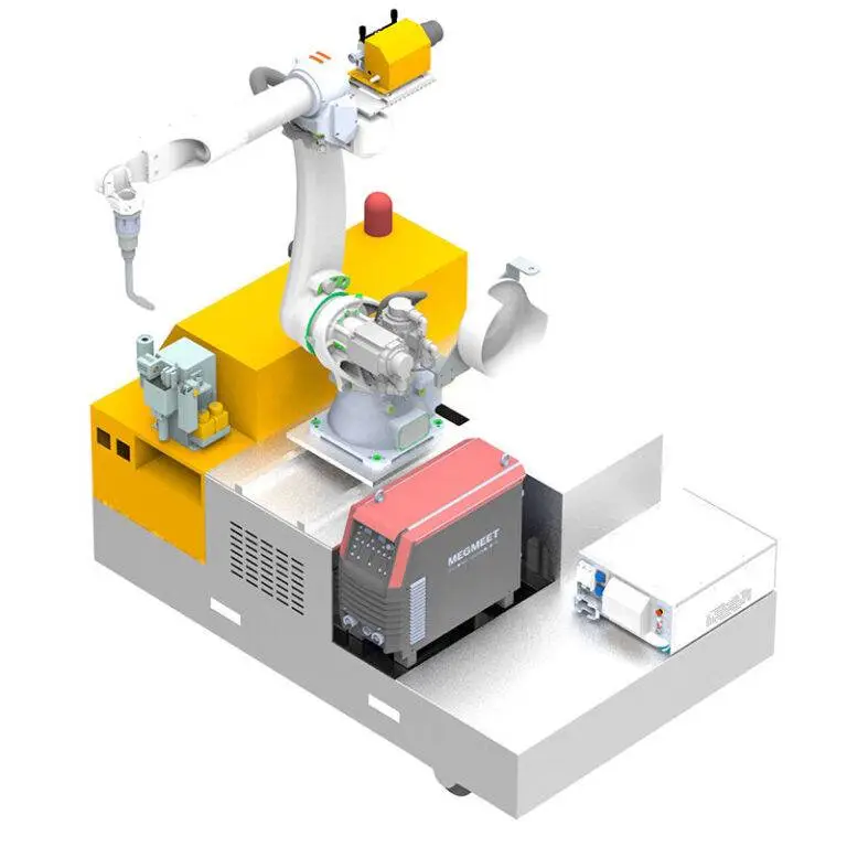
The core of the installation is a 6-axis collaborative arm integrated with a high-speed welding package. Unlike traditional industrial robots, the MAG Cobot Welder was selected for its small footprint and the ability for human operators to work alongside the unit without expensive light curtains or physical fencing, which was a logistical requirement given the cramped floor layout of the Chennai plant.
2.1 Hardware Synergy
The synergy between the MAG Cobot Welder and our specialized Arc Welding Solutions is centered on the digital communication interface. We utilized a high-speed EtherCAT bridge between the cobot controller and the 500A inverter power source. This allows for real-time adjustments of wire feed speed (WFS) and voltage (trim) during the weld sequence. In the context of Copper Components welding, this micro-second responsiveness is critical to prevent burn-through or lack of fusion at the start of the bead.
3.0 Technical Application: Copper Components Welding
Welding copper and its alloys using a MAG process is notoriously difficult due to the material’s high thermal conductivity (approx. 400 W/m·K). Standard MAG processes, typically used for steel, often fail here because the heat is wicked away from the weld pool faster than it can be applied, leading to “cold starts.”
3.1 Overcoming Thermal Diffusivity
To address this, we implemented a “Hot Start” protocol within our Arc Welding Solutions stack. The MAG Cobot Welder was programmed to deliver a 25% current surge for the first 150ms of the arc ignition. This overcomes the initial heat sink effect of the copper busbars. We utilized a Copper-Silicon (CuSi3) filler wire, technically moving into the realm of MIG/MAG brazing, which provides excellent wetting characteristics while maintaining the electrical conductivity required by the client’s specifications.
3.2 Gas Dynamics in Humid Environments
In the Chennai facility, atmospheric moisture was causing porosity in the copper welds. We modified the gas delivery system to use a 2% O2 / 98% Ar mix, providing the “Active” component necessary for the MAG classification. This mixture stabilized the cathode spot on the copper surface. We also installed inline gas heaters to ensure the shielding gas remained above the dew point, preventing moisture condensation within the torch liner.
4.0 Integration of Arc Welding Solutions
The term “Arc Welding Solutions” at this site refers to more than just the power source; it encompasses the torch geometry, the wire delivery system, and the sensory feedback loops. For the MAG Cobot Welder, we employed a push-pull torch system. Since copper wire is softer than steel, a standard push-only system resulted in “bird-nesting” at the feed rollers due to the friction in the 4-meter cable run.
4.1 Torch Calibration and TCP
Tool Center Point (TCP) calibration was performed every 50 cycles using an automated “touch-sense” routine. Given the high speeds of the MAG Cobot Welder, even a 0.5mm deviation in the contact tip-to-work distance (CTWD) would result in significant spatter when working on Copper Components welding. The integrated Arc Welding Solutions software allowed the cobot to compensate for workpiece thermal expansion—a common issue when welding copper, which expands significantly during the process.
5.0 Performance Metrics and Results
After a six-week evaluation period, the following data points were recorded:
- Cycle Time Reduction: The MAG Cobot Welder reduced cycle times by 42% compared to manual GTAW/GMAW processes.
- Defect Rate: Rejection due to porosity in Copper Components welding dropped from 12% to less than 1.5%.
- Uptime: The system maintained a 94% uptime, with the primary downtime being scheduled nozzle cleaning and tip replacement.
6.0 Lessons Learned: Engineering Observations
The Chennai deployment provided several “hard-won” lessons that should be standardized for future Arc Welding Solutions rollouts in the Indian subcontinent.
6.1 The Humidity Factor
Never underestimate the impact of humidity on wire feed consistency. Even with the MAG Cobot Welder‘s precision, if the wire picks up surface moisture, the hydrogen levels in the weld pool will spike. We had to implement pressurized, climate-controlled wire drums (pay-off packs) to ensure the filler metal remained pristine.
6.2 Grounding and High-Frequency Interference
Copper is an excellent conductor not just for heat, but for electricity. We found that the grounding (earthing) of the workpiece needed to be significantly more robust than steel applications. Floating grounds caused intermittent feedback errors in the cobot’s encoders. We moved to a dual-point rotary ground clamp to ensure a stable return path during the high-speed movements of the MAG Cobot Welder.
6.3 Operator Skill Shift
A significant observation was the shift in labor requirements. The manual welders in the Chennai plant were initially skeptical. However, once they realized the MAG Cobot Welder was a tool to handle the “dirty” work of Copper Components welding (high UV exposure and intense heat), they transitioned into “Cobot Technicians.” The lesson here: the success of Arc Welding Solutions depends as much on the UI/UX as it does on the weld metallurgy.
7.0 Synergy Evaluation: Cobot vs. Process
The synergy between the MAG Cobot Welder and the Arc Welding Solutions is most evident in the “Through-Arc Seam Tracking” (TAST). In welding copper, the puddle is fluid and highly reflective, making optical tracking difficult. By using TAST, the power source monitors the electrical characteristics of the arc and feeds that data back to the cobot to adjust its path in real-time. This is the only way to maintain a consistent bead profile on non-linear copper joints where thermal warping is a factor.
8.0 Conclusion
The implementation in Chennai proves that the MAG Cobot Welder is a viable solution for the challenging arena of Copper Components welding, provided it is backed by a comprehensive suite of Arc Welding Solutions. The key to success was not the robot itself, but the integration of environment-specific hardware (gas heaters, push-pull feeders) and material-specific software (pulse-on-pulse curves for copper). Future installations will focus on further automating the pre-heating phase using induction coils integrated into the cobot’s logic controller.
Prepared by:
Senior Welding Engineer
Field Operations Division – South Asia