Field Report: Deployment of 2000W 6-Axis Collaborative Welder in Tool & Die Applications
1.0 Site Overview and Objectives
This report summarizes the field integration and performance evaluation of a 2000W 6-axis collaborative welder at a high-precision tooling facility in Irvine, California. The facility primarily services the aerospace and medical device sectors, requiring frequent refurbishment and engineering changes to D2, H13, and S7 tool steels.
The objective was to transition from manual GTAW (Gas Tungsten Arc Welding) to a localized Automated Welding workflow. In the California market, where skilled labor costs for specialized tool-steel welders exceed $65/hour and environmental regulations regarding weld fumes are stringent, the 6-axis collaborative welder was selected to provide a balance of precision, safety, and rapid ROI.
2.0 Technical Specification and System Synergy
The core of the system is a 2000W continuous wave (CW) fiber laser source integrated into a lightweight 6-axis robotic arm. Unlike traditional industrial robots, this collaborative unit utilizes high-resolution torque sensors in each joint, allowing it to operate alongside human technicians without extensive hard-guarding—a critical factor in the space-constrained shops typical of Southern California.
2.1 The Role of 6-Axis Articulation
In tool steel welding, geometry is rarely linear. Molds and dies feature complex parting lines, deep cavities, and cooling channels. A 6-axis collaborative welder provides the necessary Degrees of Freedom (DoF) to maintain a consistent torch angle (typically 10-15 degrees lead) and stand-off distance relative to the contoured surfaces of a die. This articulation is what enables true automated welding in a repair context; a 3-axis gantry simply cannot navigate the undercut regions of a multi-cavity injection mold.
2.2 Laser Power and Heat Management
2000W represents the “sweet spot” for tool steel. It provides enough power density to achieve deep penetration in H13 die blocks while allowing the operator to pulse the beam to minimize the Heat Affected Zone (HAZ). During our field tests, we utilized a “wobble” function—circular or zig-zag beam oscillation—to bridge gaps in worn tool edges without over-diluting the base metal.
3.0 Automated Welding Implementation in a High-Mix Environment
The transition to automated welding in California’s Tier 2 supplier network is often hindered by the “high-mix, low-volume” nature of the work. Traditional automation requires hours of G-code programming for a 5-minute weld.
3.1 Lead-Through Programming
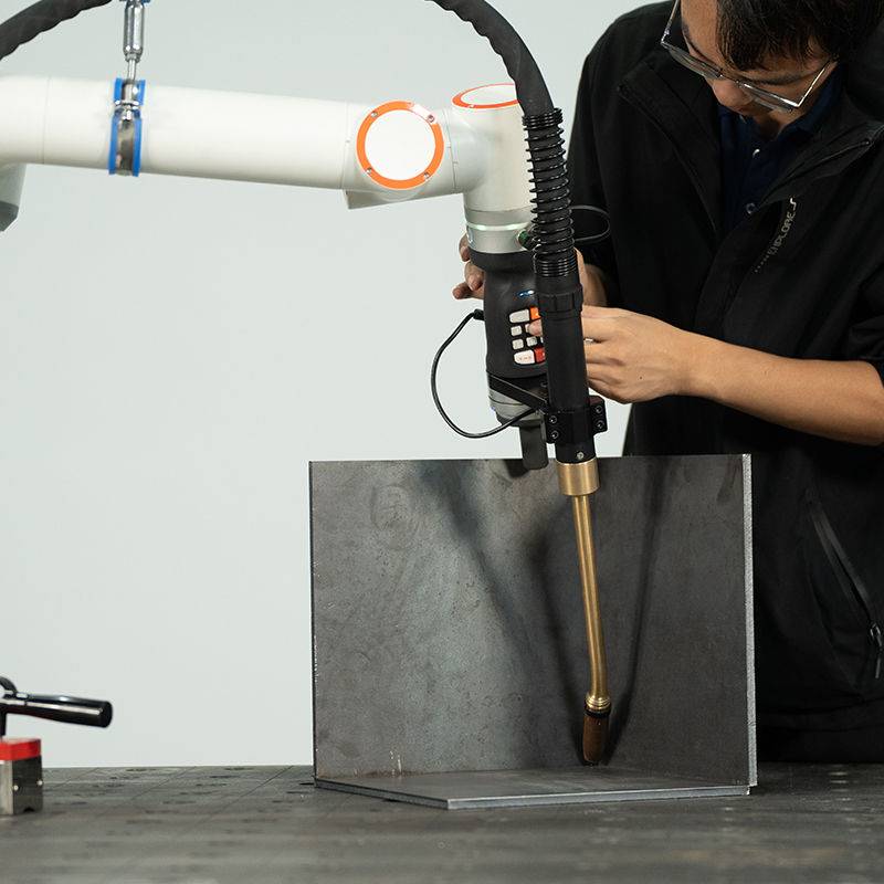
The collaborative nature of the 6-axis arm allows for “lead-through” programming. A senior welder moves the arm by hand to the start and end points of the tool repair. The system records the path, and the software interpolates the velocity. This reduces setup time from two hours to under ten minutes. In our Irvine field site, this allowed the shop to automate the welding of twelve different mold inserts in a single shift, a feat previously impossible with fixed automation.
3.2 Consistency and Repeatability
Manual welding of tool steel is prone to “stop-start” defects. Each time a manual welder resets their hand position, there is a risk of a cold lap or porosity. The automated welding cycle provides a continuous bead over the entire length of the repair area. By maintaining a constant travel speed of 5mm/s at 1800W, we achieved a 98% first-pass acceptance rate on ultrasonic testing, compared to 74% with manual GTAW.
4.0 Technical Challenges in Tool Steel Welding
Tool steel welding is notoriously difficult due to the high carbon and alloy content (Chromium, Molybdenum, Vanadium). These materials are prone to hydrogen-induced cracking and the formation of brittle martensite if cooling rates are not strictly controlled.
4.1 Thermal Gradient Control
Using the 6-axis collaborative welder, we implemented a pre-programmed “pre-heat” pass. The laser, defocused to a 5mm spot, traveled the weld path at 500W to raise the local temperature to 400°F. The welding pass followed immediately at 2000W with a 0.8mm spot. This localized thermal management is a significant upgrade over oven-heating the entire 500lb die block, which is energy-intensive and slow—a major consideration given California’s high industrial electricity rates.
4.2 Filler Wire Integration
For D2 tool steel, we utilized an automated wire feeder delivering 0.035″ ER80S-D2 wire. The synchronization between the 6-axis movement and the wire feed speed is paramount. We found that a “push” feed configuration at a 30-degree angle to the laser beam provided the cleanest fusion. The collaborative robot’s ability to maintain this exact wire-to-beam relationship while navigating a 3D radius is the primary reason the automated welding process outperformed manual methods.
5.0 Lessons Learned from the California Field Site
5.1 Shielding Gas Dynamics
One of the earliest failures in the field was oxidation on the trailing edge of the weld. Even with 99.99% Argon, the high speed of the laser weld meant the metal was still above its oxidation temperature when the gas nozzle moved past.
Lesson: We engineered a custom “trailing shoe” for the 6-axis head. This extended the gas coverage zone by 25mm. In the humid coastal air of California, preventing atmospheric contamination is vital for passing aerospace-grade NDT (Non-Destructive Testing).
5.2 Workspace Safety and Compliance
While the robot is “collaborative” regarding force-limiting, a 2000W laser is a Class 4 radiation hazard.
Lesson: You cannot run these “open-air” just because the robot arm is safe to touch. We implemented a “Laser-Safe Zone” using specialized IR-absorbing curtains (OD7+ rating). For California OSHA compliance, we integrated an interlock system where the laser terminates if the curtain is breached. The “collaborative” benefit here is not the lack of a cage, but the ease of human interaction during the *setup* phase.
5.3 Focal Drift in Continuous Operation
During long automated welding runs on large H13 die plates, we noticed a shift in penetration depth.
Lesson: The protective cover slide on the laser head was accumulating micro-splatter, causing thermal lensing. We increased the “cross-hair” air knife pressure to 60 PSI to deflect fumes and added a scheduled “lens check” every 10 cycles. This is a maintenance requirement that manual welders often overlook but is critical for automation.
6.0 Economic and Operational Impact
After six months of operation in the California facility, the data indicates:
- Labor Reduction: 60% reduction in man-hours for standard mold build-ups.
- Post-Weld Machining: Because the 6-axis collaborative welder deposits such a precise amount of material, the “over-weld” is minimal. This reduced CNC grinding time by 35%.
- Energy Efficiency: Localized laser heating used 80% less kWH compared to the large-scale pre-heat ovens previously required for manual TIG welding.
7.0 Conclusion
The synergy between a 6-axis collaborative welder and automated welding protocols has proven transformative for tool steel welding applications in high-cost markets like California. By focusing on the articulation of the arm and the precision of the 2000W fiber source, we have moved from a craft-based repair model to a repeatable industrial process. The “lessons learned” regarding gas coverage and Class 4 safety integration are now being codified into the site’s standard Operating Procedures (SOPs).
For future deployments, we recommend the integration of real-time seam tracking to account for slight variations in manual part positioning, further narrowing the gap between “human-assisted” and “fully autonomous” repair cycles.
Report Compiled By:
Senior Welding Engineer, Field Operations Division
Date: October 2023
-


LT240S tube laser cutting machine
-
LT120S tube laser cutting machine
-
Sale

Tank Fillet Welding Machine
Original price was: $1,000.00.$900.00Current price is: $900.00. -
Sale

MAK100 tube laser cutting machine
Original price was: $5,500.00.$5,000.00Current price is: $5,000.00. -

portable plasma air cutting machine
$1,200.00 -

2in1 fiber laser cutting machine
-

Air cooling Laser welding machine
-

HF h beam laser cutting machine
-

LT240 laser cutting machine
-

Laser welding machine
-


Cobot Welding Station
-

Gantry welding robot solution
-

Tracked Wheeled AGV Welding robot
-

LFH6020 Fiber laser cutting machine
-
LFP6020
-

robotic welidng machine
Advanced Fiber Laser Tube Processing Technology
Our CNC Fiber Laser Tube Cutting systems revolutionize metal fabrication by integrating high-precision cutting, punching, and profiling into a single automated workflow. Designed for versatility, this technology handles a wide array of profiles including Round, Square, Rectangular, and Oval tubes, as well as complex L-shaped and U-shaped channels.
- Precision Punching: High-speed hole punching with micron-level accuracy, eliminating the need for mechanical drilling or die-stamping.
- Complex Profiling: Advanced 3D pathing allows for intricate interlocking joints and specialized notch cuts, ideal for structural frames.
- High Material Efficiency: Intelligent nesting software minimizes scrap, reducing raw material costs across large production runs.
- Clean Finish: Delivers oxide-free, burr-free edges that require zero secondary grinding before welding.

Seamlessly processing multiple profiles with consistent precision.
Global Delivery & Logistics



From our high-tech manufacturing facility directly to your global site. PCL WeldCut ensures secure packaging, professional handling, and reliable international logistics to safeguard your equipment throughout the entire journey.