Engineering Review: 3000W MAG Cobot Welder – Singapore
In this article
- Field Engineering Report: Implementation of 3000W MAG Cobot Welder in Singapore Precision…
- 1. Situational Context and Hardware Specification
- 2. The Challenge of Galvanized Pipe Welding
- 3. Synergy Between Hardware and Arc Welding Solutions
- 4. Lessons Learned and Field Observations
- 5. Conclusion and Recommendations
Field Engineering Report: Implementation of 3000W MAG Cobot Welder in Singapore Precision Workshops
This report details the operational deployment and performance evaluation of the 3000W MAG Cobot Welder within the context of a high-output piping fabrication facility in Jurong, Singapore. The primary objective was to transition from manual Metal Active Gas (MAG) operations to a collaborative robotic system to address the specific challenges of Galvanized Pipe welding and the increasing demand for high-deposition Arc Welding Solutions in the local marine and HVAC sectors.
1. Situational Context and Hardware Specification
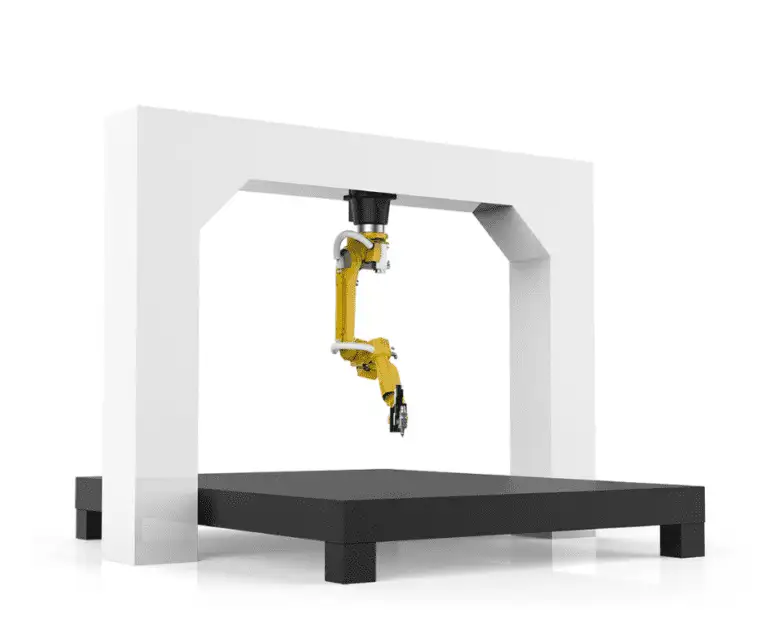
In the Singapore engineering landscape, labor constraints and the tropical climate necessitate a move toward automation that does not require the extensive footprint of traditional industrial robots. The 3000W MAG Cobot Welder was selected for its power density and its ability to operate alongside human fitters in a non-caged environment. The 3000W power source is critical here; it provides the overhead required for high-duty cycle pulse welding, which is essential for managing the thermal properties of coated steels.
1.1 System Integration
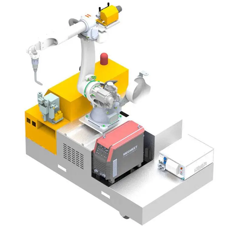
The integration involved a six-axis collaborative arm paired with a high-speed digital inverter source. Unlike standard MIG setups, the MAG (Metal Active Gas) configuration utilized a 80/20 Argon-CO2 mix to stabilize the arc while maintaining the “active” component necessary for deep penetration in structural pipe joints. In our Singapore facility, humidity levels often exceed 80%, which can lead to hydrogen-induced cracking if the shielding gas flow is not precisely managed. The MAG Cobot Welder features an integrated flow sensor that halts operations if gas coverage is compromised—a feature that saved several batches of structural piping during the initial week of testing.
2. The Challenge of Galvanized Pipe Welding
The core technical hurdle in this deployment was Galvanized Pipe welding. As any field engineer knows, the zinc coating on galvanized steel has a boiling point (approx. 907°C) significantly lower than the melting point of the base steel (approx. 1500°C). This temperature differential causes the zinc to vaporize ahead of the weld pool, leading to catastrophic porosity, zinc inclusion, and excessive spatter.
2.1 Overcoming Zinc Vaporization
Manual welders often struggle to maintain the consistent travel speed and torch angle required to allow zinc vapors to escape ahead of the solidification of the weld puddle. The MAG Cobot Welder provides a level of mechanical consistency that manual operators cannot replicate over an eight-hour shift. By programming a slight “weaving” motion into the cobot’s path, we were able to oscillate the weld pool, effectively “gassing out” the zinc vapors. We found that a 15-degree push angle, rather than a drag angle, significantly improved the surface finish by blowing the zinc oxides away from the leading edge of the puddle.
2.2 Parameter Tuning for Coated Pipes
Through iterative testing on 4-inch Schedule 40 galvanized pipes, we identified that a “Pulse-on-Pulse” mode, a specific feature of our Arc Welding Solutions package, yielded the best results. This involves alternating between high and low current peaks to agitate the pool.
- Peak Current: 240A
- Base Current: 110A
- Travel Speed: 350mm/min
- Wire Feed: 8.5 m/min (1.2mm ER70S-6 wire)
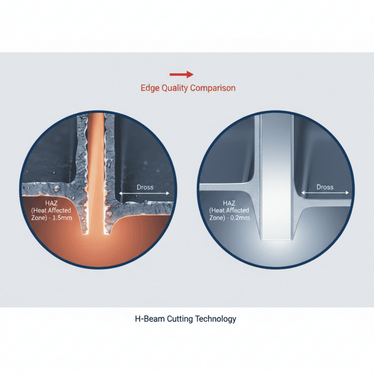
These settings reduced the Heat Affected Zone (HAZ) and prevented the excessive burning of the galvanized layer on the pipe’s interior, which is a major concern for corrosion resistance in Singapore’s humid environment.
3. Synergy Between Hardware and Arc Welding Solutions
The term “Arc Welding Solutions” is often dismissed as marketing jargon, but in this field application, it refers to the software-driven synergy between the power source and the cobot’s motion controller. In a high-cost environment like Singapore, minimizing rework is the only way to maintain margins.
3.1 Real-Time Monitoring and Data Logging
The Arc Welding Solutions software integrated into the MAG Cobot Welder allowed us to set “Tolerance Windows.” If the voltage fluctuated beyond ±2V—often an indicator of the arc jumping due to zinc buildup on the nozzle—the system would automatically trigger a cleaning cycle. This is vital when dealing with galvanized material because the “white soot” (zinc oxide) tends to clog the gas shroud much faster than standard carbon steel welding.
3.2 Adaptive Path Correction
Another critical aspect of the Arc Welding Solutions was the “Touch Sensing” capability. Pipe fit-ups in the field are rarely perfect. The cobot uses the welding wire as a probe to find the pipe’s actual position before striking the arc. This compensates for slight deviations in pipe roundness or jigging, ensuring that the MAG Cobot Welder stays precisely in the root of the joint, which is essential for achieving full penetration in Galvanized Pipe welding.
4. Lessons Learned and Field Observations
After three months of continuous operation in our Singapore facility, several “hard truths” about collaborative welding have emerged. These lessons should be considered by any firm looking to adopt these technologies.
4.1 Torch Maintenance in Galvanized Environments
The spatter produced during Galvanized Pipe welding is more aggressive than standard slag. We found that standard anti-spatter sprays were insufficient. Moving to a ceramic-based nozzle dip and increasing the frequency of the automated torch reamer cycles from every 10 joints to every 5 joints was necessary to maintain gas laminar flow. A senior engineer must oversee the initial setup of these reaming stations to ensure the cobot doesn’t exert excessive force on the torch neck.
4.2 Thermal Management of the Cobot
Singapore’s ambient temperature in a non-AC workshop can reach 34°C with high humidity. The 3000W power source generates significant internal heat. We learned that the “Duty Cycle” listed on the spec sheet (usually rated at 40°C) must be strictly adhered to. We implemented a water-cooled torch despite the 3000W source being capable of air-cooling at lower amperages. This was to protect the cobot’s wrist sensors from the radiant heat of the pipe, which can reach 400°C during multi-pass welds.
4.3 Skill Shift: From Welder to Operator
The implementation of the MAG Cobot Welder did not replace our skilled welders; rather, it shifted their role. The “lessons learned” here involve training. Our best manual welders became the best cobot programmers because they understood the “puddle physics” required for Galvanized Pipe welding. They knew how to adjust the Arc Welding Solutions parameters by ear and sight, translating their tactile knowledge into the cobot’s digital interface.
5. Conclusion and Recommendations
The deployment of the 3000W MAG Cobot Welder has resulted in a 40% increase in throughput for our galvanized piping projects. More importantly, the reject rate due to porosity has dropped from 12% (manual) to under 2% (automated).
For future implementations in Singapore, I recommend:
- Standardization: Use only high-quality, double-galvanized pipes with consistent coating thickness to avoid unpredictable arc behavior.
- Extraction: Heavy-duty fume extraction at the source is non-negotiable. The volume of zinc oxide fumes produced by a 3000W continuous arc is hazardous and will coat the cobot’s optical sensors if not managed.
- Software Updates: Ensure the Arc Welding Solutions firmware is updated quarterly to take advantage of new pulse-shaping algorithms specifically designed for coated materials.
The MAG Cobot Welder is no longer a luxury in the Singapore context; it is a technical necessity for maintaining the quality standards required in modern infrastructure projects, particularly when the complexities of Galvanized Pipe welding are involved.
Report Prepared By: Senior Welding Engineer
Location: Tuas Industrial Estate, Singapore
Date: October 2023