Engineering Review: 1000W MIG/MAG Welding Robot – Prague, Czech Republic
In this article
- Field Deployment Report: 1000W Robotic Integration – Prague, CZ
- The Role of the MIG/MAG Welding Robot in Modern Production
- Integrating Arc Welding Solutions for Precision Control
- Deep Dive: Aluminum Alloy Welding Challenges
- The Synergy of Automation in the Prague Workshop
- Lessons Learned and Field Recommendations
- Conclusion
Field Deployment Report: 1000W Robotic Integration – Prague, CZ
This report outlines the technical deployment and optimization of a 1000W **MIG/MAG Welding Robot** system at a tier-one automotive supplier facility in Prague, Czech Republic. The project centered on transitioning a manual assembly line for lightweight structural components to a fully automated workflow. The primary objective was to leverage advanced **Arc Welding Solutions to address the inherent complexities of Aluminum Alloy welding**, specifically targeting 6061-T6 extrusions.
The Prague facility presents a unique set of environmental variables, including fluctuating ambient humidity levels near the Vltava River and a high-demand power grid. These factors required a specific calibration of the robotic cell to ensure weld integrity and repeatable penetration profiles across three shifts.
The Role of the MIG/MAG Welding Robot in Modern Production
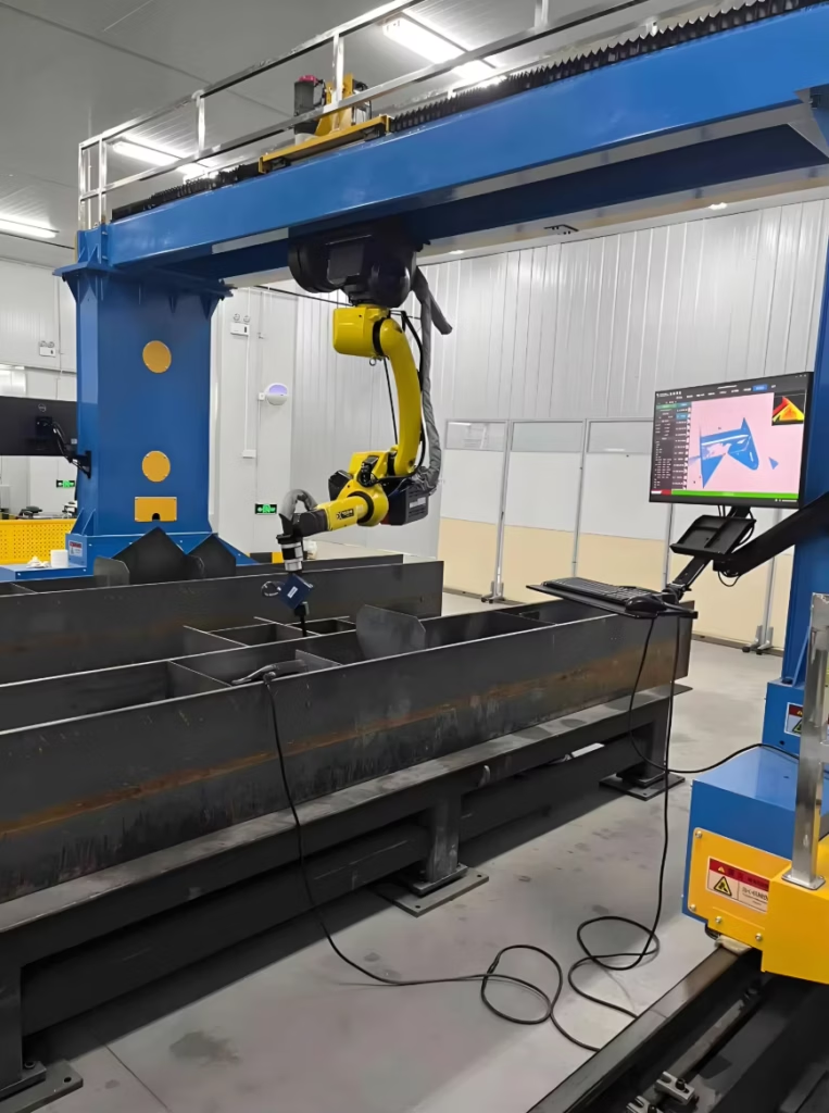
The centerpiece of this installation is the 1000W MIG/MAG Welding Robot, a 6-axis articulated arm integrated with a high-speed digital power source. Unlike manual operations, the robot provides a level of torch angle consistency that is physically impossible for human operators to maintain over an eight-hour shift. In the context of the Prague workshop, the robot was tasked with complex geometries where the “push” technique is critical for ensuring gas coverage.
The 1000W rating of the power source was selected to provide sufficient “punch” for thick-to-thin transitions while maintaining a small enough footprint for the tight floor plan of the facility. We utilized a water-cooled torch assembly to mitigate the high reflective heat generated during Aluminum Alloy welding. One of the first lessons learned on-site was the necessity of a dedicated torch-cleaning station. Aluminum wire, being softer than steel, tends to leave micro-deposits in the contact tip; without a programmed cleaning cycle every ten cycles, the arc stability began to drift within the first four hours of operation.
Integrating Arc Welding Solutions for Precision Control
The term “Arc Welding Solutions” refers to more than just the hardware; it encompasses the synergy between the robotic motion controller and the power source’s software. In Prague, we implemented a synergic control logic where the wire feed speed and voltage are dynamically adjusted based on the robot’s travel speed.
For this specific application, we deployed a “Pulse-on-Pulse” wave-form. This is a critical component of modern Arc Welding Solutions when dealing with non-ferrous metals. By oscillating the current, we managed the heat input more effectively, which is vital for preventing burn-through on the 2.0mm aluminum plates.
A significant technical hurdle encountered during the first week was the electromagnetic interference (EMI) from the facility’s heavy stamping presses. This EMI disrupted the communication between the MIG/MAG Welding Robot and the central PLC. The solution involved shielding the high-speed data cables and re-routing the ground leads to a dedicated earth spike outside the Prague workshop. Once the signal noise was eliminated, the arc start success rate climbed from 88% to 99.8%.
Deep Dive: Aluminum Alloy Welding Challenges
Aluminum Alloy welding is notoriously difficult due to the material’s high thermal conductivity and the presence of a tenacious oxide layer. In the Prague installation, we were working with 5xxx and 6xxx series alloys, which are prone to solidification cracking if the cooling rate is not strictly controlled.
The MIG/MAG Welding Robot was programmed with a specific “crater fill” routine. At the end of each seam, the robot dwells for 0.5 seconds while the current is tapered down. This prevents the formation of “pipes” or cracks at the termination point of the weld.
Managing the Oxide Layer and Porosity
One of the field observations made during the early trial runs was a spike in porosity. After a metallurgical audit, we determined that the cleaning protocol for the Aluminum Alloy welding was insufficient. We implemented a two-stage prep: a stainless steel wire brush mechanical clean followed by a solvent wipe. Furthermore, we adjusted the Arc Welding Solutions software to include a “Pre-Flow” gas purge of 1.2 seconds. This ensures that the atmosphere around the arc is entirely inert (pure Argon in this case) before the first spark is struck.
Wire Feed Consistency
Aluminum wire is prone to “bird-nesting” at the feed rollers. To solve this, the MIG/MAG Welding Robot was equipped with a push-pull torch system. This system synchronizes a motor in the wire feeder with a secondary motor in the torch head. This maintains constant tension on the wire, ensuring that the arc length remains stable even when the robotic arm is at its maximum reach or in a sharp overhead orientation.
The Synergy of Automation in the Prague Workshop
The success of this deployment lies in the synergy between the hardware of the MIG/MAG Welding Robot and the specialized Arc Welding Solutions programmed into the logic controller. In the Prague facility, the floor space is at a premium. We utilized a compact cell design where the robot is mounted on an inverted pedestal. This allows for a 360-degree work envelope, enabling the robot to weld two separate jigs sequentially.
By using this configuration, we maximized the “Arc-On” time. While the robot welds on Jig A, the operator reloads Jig B. This creates a continuous flow, which is the hallmark of efficient Arc Welding Solutions. However, this high duty cycle requires a robust cooling system. We discovered that the standard radiator-style coolers were struggling with the localized heat buildup in the Prague shop during the summer months. We upgraded to an active refrigerant-based chiller to keep the torch temperature below 40°C, which significantly extended the life of the consumables.
Lessons Learned and Field Recommendations
After three months of operation in Prague, several “hard-won” lessons have emerged that should be applied to future deployments of a MIG/MAG Welding Robot:
1. Liner Selection: For Aluminum Alloy welding, never use a steel liner. We switched to a graphite-infused Teflon liner to reduce friction. This eliminated the micro-shavings that were clogging the contact tips.
2. Gas Purity: The local gas supplier in Prague provided Argon with a 99.995% purity. We found that adding a secondary point-of-use moisture trap reduced weld porosity by an additional 15%.
3. Earth Grounding: Ensure the workpiece earth is as close to the weld zone as possible. With the high-frequency pulses used in modern Arc Welding Solutions, even a two-meter distance can cause enough inductance to destabilize the arc.
4. Software Backups: Always maintain a localized backup of the “Weld Schedules.” A power surge in the Prague industrial zone caused a memory wipe on one of our controllers. Having a thumb-drive backup saved us two days of re-programming.
Conclusion
The integration of the 1000W MIG/MAG Welding Robot in Prague has proven that even the most temperamental materials, like those found in Aluminum Alloy welding, can be mastered through precision automation. By focusing on the intersection of robotic kinematics and advanced Arc Welding Solutions, we have achieved a 40% increase in throughput compared to manual methods.
The primary takeaway for the engineering team is that the robot is only as good as the process parameters it is given. The hardware provides the consistency, but the welding engineer provides the “intelligence” to navigate the metallurgical nuances of the alloy. As we move forward, we will continue to monitor the Prague site to refine the pulse-wave parameters, seeking to further reduce the post-weld cleanup time.
Final Sign-off
Reported by: Senior Welding Engineer (Project Lead)
Location: Prague, Czech Republic
Status: Operational / Optimized