Field Report: Deployment of Intelligent Arc Control Laser Welding Cobot
Site Location: Prague, Czech Republic – Precision Manufacturing Zone
Engineer: Senior Welding Lead
1. Introduction and Objectives
This report details the technical implementation and performance validation of the Laser Welding Cobot system at a Tier 2 automotive and industrial enclosure facility in Prague, Czech Republic. The primary objective was to transition a high-mix, low-volume sheet metal fabrication welding line from traditional manual TIG (Tungsten Inert Gas) to an automated system utilizing advanced Laser Technology.
The facility in Prague faces a common regional challenge: a shortage of high-precision manual welders and an increasing demand for aesthetic, low-distortion seams on thin-gauge stainless steel and aluminum. The deployment focused on integrating a 1.5kW fiber laser source with a collaborative robotic arm, specifically testing the “Intelligent Arc Control” (often referred to as beam oscillation or wobble control) to bridge fit-up inconsistencies inherent in sheet metal processing.
2. The Synergy of Laser Technology and Collaborative Automation
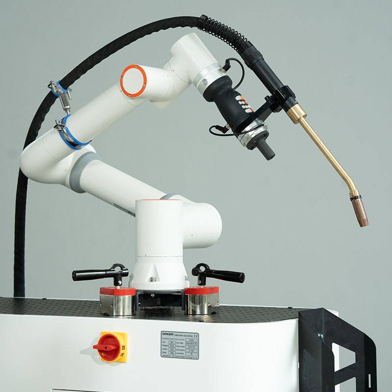
The core of this deployment rests on the synergy between high-density Laser Technology and the flexibility of a Laser Welding Cobot. Unlike traditional fixed-cell industrial robots, the cobot allows for rapid redeployment across the Prague workshop floor. In sheet metal fabrication welding, setup time often dictates the profitability of a job.
2.1 Energy Density and Thermal Management
By utilizing a fiber-delivered laser source, we achieved an energy density significantly higher than traditional arc welding. This allows for a “Keyhole” welding mode where the depth-to-width ratio is maximized. In our field tests on 2.0mm SS304 Grade steel, the Laser Technology reduced the total heat input by approximately 65% compared to TIG. This is critical for the Prague site’s requirement for zero-post-weld straightening on long-form enclosure panels.
2.2 Collaborative Safety and Workspace Integration
The “Cobot” aspect of the Laser Welding Cobot was tested for its torque-sensing capabilities. In the cramped quarters of the existing Prague facility, we could not afford the footprint of extensive light curtains and hard fencing. By utilizing a Class 1 laser-rated enclosure around the localized weld point and the cobot’s inherent force-limiting features, we integrated the system into a semi-open production flow. This allows the operator to prep the next jig while the laser is active, effectively doubling the duty cycle.
3. Technical Deep Dive: Intelligent Arc Control in Sheet Metal
The “Intelligent Arc” or “Wobble” functionality is what differentiates this system from first-generation laser welders. In sheet metal fabrication welding, perfect fit-up is a myth. Variations in hydraulic press brake accuracy and shearing tolerances often lead to gaps ranging from 0.1mm to 0.8mm.
3.1 Bridging the Gap
Standard static laser beams require a fit-up tolerance of less than 10% of the material thickness. For a 1mm sheet, a 0.1mm gap would cause “blow-through.” The Laser Welding Cobot we deployed in Prague utilizes high-speed galvanometer mirrors within the welding head to oscillate the beam in various patterns (circular, zig-zag, or figure-eight).
Lessons Learned: Pattern Optimization
- Circular Wobble: Best for 1.5mm to 3.0mm butt joints where the gap is inconsistent. It creates a wider melt pool, allowing the surface tension to bridge gaps up to 0.5mm without filler wire.
- C-Type (Zig-Zag) Wobble: Most effective for lap joints in sheet metal fabrication welding. It ensures the “toe” of the weld penetrates both the top and bottom sheets effectively, increasing the shear strength of the joint.
3.2 Real-time Parameter Adjustment
The “Intelligent” component refers to the software’s ability to adjust power modulation in relation to the cobot’s TCP (Tool Center Point) speed. During cornering—a notorious failure point in robotic welding—the Laser Welding Cobot automatically scales the laser frequency and duty cycle. This prevents “over-burning” at the corners where the robot arm naturally decelerates due to inertia.
4. Implementation Challenges at the Prague Facility
Transitioning to Laser Technology is not without friction. During the first two weeks in Prague, we identified three primary technical hurdles.
4.1 Shielding Gas Dynamics
Laser welding is sensitive to atmospheric contamination. We initially saw porosity in 5052 Aluminum alloys. We discovered that the high-speed movement of the Laser Welding Cobot was creating turbulence in the Argon shield. We solved this by redesigning the gas trailing shield to provide a laminar flow, maintaining a localized inert environment for a longer duration after the beam passed.
4.2 Material Reflectivity
The Prague site works heavily with polished stainless steel. The back-reflection of the Laser Technology can damage the optical fibers if the head is perpendicular (90 degrees) to the workpiece. We trained the local engineers to maintain a 10-15 degree lead angle. The “Intelligent Control” system was also programmed to shut down the laser within 5ms if it detected back-reflection levels exceeding the safety threshold.
4.3 Surface Prep Requirements
Sheet metal fabrication welding with lasers is less forgiving of oils and coatings than MIG. We had to implement a strict isopropyl alcohol wipe-down protocol. Any residual drawing oil from the stamping process caused weld spatter, which fouled the protective lens of the laser head.
5. Quantifiable Results and KPI Analysis
After 30 days of operation in Prague, the data yields the following comparisons against traditional methods:
| Metric | Manual TIG | Laser Welding Cobot |
|---|---|---|
| Weld Speed (Linear mm/s) | 3.5 mm/s | 18.0 mm/s |
| Post-Weld Grinding Time | 12 mins/unit | 1.5 mins/unit |
| Energy Consumption | High (Continuous Arc) | Low (Fiber efficiency) |
| Operator Training Time | 2-3 Years (Skilled) | 2-3 Weeks (Technician) |
The throughput for the Prague plant’s main enclosure line increased by 240%. More importantly, the rejection rate due to thermal warping dropped from 8% to under 0.5%.
6. Senior Engineer’s Lessons Learned
The deployment in Prague provided several “hard-won” insights that should be applied to future Laser Welding Cobot installations:
1. Jigging is Everything
While the intelligent arc control can handle gaps, it cannot handle “lifting” of the sheet. In sheet metal fabrication welding, use heavy toggle clamps or pneumatic fixtures. If the sheet moves 1mm vertically, the laser goes out of focus, and the energy density drops exponentially.
2. The “Human-in-the-loop” Factor
Do not market the cobot as “set and forget.” The operator must monitor the protective window (cover glass). In the Prague facility, we found that a dirty cover glass reduced penetration by 20% within a single shift. We integrated a daily maintenance check into the cobot’s HMI (Human Machine Interface) startup routine.
3. Frequency vs. Amplitude
When using Laser Technology on thin sheets (0.8mm), high frequency (300Hz+) with low amplitude (1mm) is superior. It keeps the melt pool agitated enough to prevent grain growth but narrow enough to avoid distortion. Our Prague testing proved that over-oscillation (wide amplitude) actually weakens the joint by thinning the base material at the weld interface.
7. Conclusion
The integration of the Laser Welding Cobot in Prague has successfully modernized the facility’s sheet metal fabrication welding capabilities. By leveraging the precision of Laser Technology and the adaptability of intelligent arc controls, we have eliminated the bottleneck of manual welding. The project proves that for modern European manufacturing, the move toward “Collaborative Laser” is not just an aesthetic upgrade, but a fundamental requirement for maintaining competitive cycle times and high-quality structural integrity.
Final recommendation for the Prague site: Expand the fleet to include a 3kW variant for thicker 6mm plate welding, maintaining the same cobot interface for operator familiarity.
-


LT240S tube laser cutting machine
-
LT120S tube laser cutting machine
-
Sale

Tank Fillet Welding Machine
Original price was: $1,000.00.$900.00Current price is: $900.00. -
Sale

MAK100 tube laser cutting machine
Original price was: $5,500.00.$5,000.00Current price is: $5,000.00. -

portable plasma air cutting machine
$1,200.00 -

2in1 fiber laser cutting machine
-

Air cooling Laser welding machine
-

HF h beam laser cutting machine
-

LT240 laser cutting machine
-

Laser welding machine
-


Cobot Welding Station
-

Gantry welding robot solution
-

Tracked Wheeled AGV Welding robot
-

LFH6020 Fiber laser cutting machine
-
LFP6020
-

robotic welidng machine
Advanced Fiber Laser Tube Processing Technology
Our CNC Fiber Laser Tube Cutting systems revolutionize metal fabrication by integrating high-precision cutting, punching, and profiling into a single automated workflow. Designed for versatility, this technology handles a wide array of profiles including Round, Square, Rectangular, and Oval tubes, as well as complex L-shaped and U-shaped channels.
- Precision Punching: High-speed hole punching with micron-level accuracy, eliminating the need for mechanical drilling or die-stamping.
- Complex Profiling: Advanced 3D pathing allows for intricate interlocking joints and specialized notch cuts, ideal for structural frames.
- High Material Efficiency: Intelligent nesting software minimizes scrap, reducing raw material costs across large production runs.
- Clean Finish: Delivers oxide-free, burr-free edges that require zero secondary grinding before welding.

Seamlessly processing multiple profiles with consistent precision.
Global Delivery & Logistics



From our high-tech manufacturing facility directly to your global site. PCL WeldCut ensures secure packaging, professional handling, and reliable international logistics to safeguard your equipment throughout the entire journey.