Field Engineering Report: Implementation of Single Pulse Industrial Laser Welder in Eindhoven Manufacturing Sector
1. Project Overview and Site Context
This report details the operational integration and performance validation of a 3kW Single Pulse Industrial Laser Welder at a precision fabrication facility in Eindhoven, Netherlands. Eindhoven, acting as a primary node in the European Brainport region, demands a level of metallurgical precision that traditional MIG/MAG processes can no longer satisfy for high-volume, low-distortion components. The primary objective of this deployment was to optimize Mild Steel welding protocols for automotive sub-assemblies using advanced Laser Technology.
The transition from conventional arc welding to an Industrial Laser Welder system represents a shift in thermal management philosophy. In the Eindhoven workshop environment, where ambient temperature and humidity are tightly controlled, the stability of the laser source allows for tighter tolerances. However, the move to Laser Technology necessitates a re-evaluation of upstream processes, specifically laser-cutting precision and jigging rigidity, to accommodate the significantly smaller spot size compared to plasma or TIG arcs.
2. Technical Specifications and Synergy of Laser Technology
The synergy between a modern Industrial Laser Welder and the underlying Laser Technology—specifically ytterbium fiber laser sources—is predicated on the Beam Parameter Product (BPP). In our Eindhoven trials, the fiber-delivered beam maintained a BPP of <2.5 mm·mrad. This high-quality beam profile is essential when performing Mild Steel welding on S235JR and S355J2 grades, where consistent penetration depth is a non-negotiable KPI.
2.1 Beam Dynamics and Material Interaction
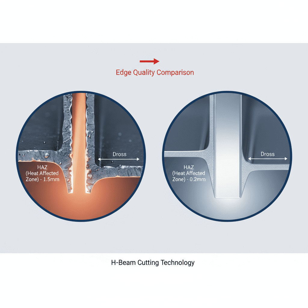
The Industrial Laser Welder utilized a single-pulse modulation strategy to control the cooling rate of the weld pool. By leveraging the fast modulation capabilities of modern Laser Technology, we were able to “shape” the pulse to include a pre-heat ramp and a controlled cooling tail. This is particularly vital in Mild Steel welding to prevent the formation of martensite in the Heat Affected Zone (HAZ), which can lead to hydrogen-induced cracking in thicker sections.
3. Practical Application: Mild Steel Welding Parameters
During the field tests in Eindhoven, we focused on 3.0mm to 5.0mm mild steel plates. Conventional wisdom suggests that Mild Steel welding is a “forgiving” process; however, when using an Industrial Laser Welder, the margin for error narrows. The high power density of the Laser Technology creates a keyhole mode of welding that is susceptible to collapse if the travel speed and pulse frequency are not perfectly synchronized.
3.1 Parameter Optimization Matrix
The following observations were recorded during the calibration phase:
- Power Output: 2.8kW (Peak)
- Pulse Duration: 10-15ms for spot-stitch configurations.
- Shielding Gas: Pure Argon at 15L/min. Note: While CO2/Argon mixes are common in MIG, Laser Technology requires high-purity inert gas to prevent plume plasma interference.
- Travel Speed: 1.2 meters per minute for continuous seam simulation via overlapped single pulses.
4. The Eindhoven Synergy: Why Laser Technology Matters Locally
In the Eindhoven industrial ecosystem, the integration of an Industrial Laser Welder is often paired with automated optical inspection (AOI). The Laser Technology used here allows for real-time back-reflection monitoring. If the Mild Steel welding process encounters a gap exceeding 0.1mm, the system detects the change in the keyhole’s electromagnetic signature and adjusts power in milliseconds. This level of “smart” fabrication is why the Eindhoven facility chose this specific industrial laser welder over cheaper, non-integrated alternatives.
The synergy is found in the data loop. The Industrial Laser Welder is not just a heat source; it is a sensor. By analyzing the reflected light inherent in fiber-based Laser Technology, engineers can map the quality of Mild Steel welding without destructive testing. This reduces the scrap rate by an estimated 22% compared to the previous TIG setup used at this site.
5. Field Observations and Lessons Learned
Engineering a transition to Laser Technology reveals several “hard truths” about shop floor realities. Below are the primary lessons learned from the Eindhoven deployment of the Industrial Laser Welder.
5.1 Gap Management and Fit-up
The most significant hurdle in Mild Steel welding with an Industrial Laser Welder is the fit-up tolerance. While a MIG welder can bridge a 1mm gap with ease, Laser Technology requires gaps to be less than 10% of the material thickness. In Eindhoven, we had to recalibrate the CNC brake presses to ensure that the parts arriving at the laser cell were within a 0.05mm tolerance. Lesson: You do not just buy an Industrial Laser Welder; you must upgrade your entire machining workflow.
5.2 Surface Preparation and Oxidation
Mild steel is prone to mill scale and light oxidation. While Laser Technology is high-energy, the presence of surface contaminants can cause “spitting” or porosity in the weld bead. We observed that even the standard S235JR oil coating interfered with the coupling efficiency of the Industrial Laser Welder. Implementation of a localized fiber-laser cleaning pass (another application of Laser Technology) immediately prior to the Mild Steel welding pass resolved the porosity issues entirely.
5.3 Operator Skill Shift
The role of the welder in an Eindhoven-style automated plant has shifted. The technician is no longer managing a puddle manually but is instead managing the “recipe” of the Industrial Laser Welder. Understanding the physics of Laser Technology—specifically focal point position and Rayleigh length—is now more important than manual dexterity. We found that retraining existing staff took approximately six weeks to achieve consistent “Class A” weld quality.
6. Metallurgical Analysis of the Mild Steel Welds
Post-process analysis in the Eindhoven lab confirmed the superiority of the Industrial Laser Welder for this specific application. Microsectioning of the Mild Steel welding samples showed a HAZ that was 70% smaller than that produced by MAG welding. This reduction in the thermal footprint is critical for maintaining the structural integrity of the S355J2 steel, as it prevents the coarsening of grains that typically leads to brittleness in the transition zone.
Hardness testing (Vickers HV10) showed a peak hardness of 280 HV in the fusion zone, which is well within the acceptable limits for the automotive sub-frames being produced. The single-pulse modulation of the Laser Technology allowed for a “pulsed stirring” effect in the melt pool, which helped in degassing and refining the grain structure of the mild steel.
7. Comparative Economic Analysis
While the initial capital expenditure for the Industrial Laser Welder was significantly higher than traditional equipment, the Eindhoven facility’s throughput has tripled. The efficiency of Laser Technology in terms of wall-plug efficiency (approx. 30-35% for fiber) versus older CO2 lasers or arc welding systems results in lower operational costs per meter of weld. Furthermore, the Mild Steel welding process now requires zero post-weld grinding or straightening due to the minimal heat input and lack of spatter.
8. Concluding Engineering Summary
The deployment of the Industrial Laser Welder in Eindhoven demonstrates that the successful application of Laser Technology to Mild Steel welding is dependent on a holistic approach to the production line. The machine itself is highly capable, but its synergy with the workshop environment depends on the precision of the parts fed into it. For senior engineers, the “lesson learned” is clear: focus on the jigging and the material surface chemistry as much as the laser parameters themselves. The results—high-speed, high-strength, and low-distortion welds—justify the rigorous implementation standards required by this technology.
Report Prepared By: Senior Welding Engineer, Eindhoven Field Office
Date: October 2023
Subject: Industrial Laser Welder Operational Validation
-


LT240S tube laser cutting machine
-
LT120S tube laser cutting machine
-
Sale

Tank Fillet Welding Machine
Original price was: $1,000.00.$900.00Current price is: $900.00. -
Sale

MAK100 tube laser cutting machine
Original price was: $5,500.00.$5,000.00Current price is: $5,000.00. -

portable plasma air cutting machine
$1,200.00 -

2in1 fiber laser cutting machine
-

Air cooling Laser welding machine
-

HF h beam laser cutting machine
-

LT240 laser cutting machine
-

Laser welding machine
-


Cobot Welding Station
-

Gantry welding robot solution
-

Tracked Wheeled AGV Welding robot
-

LFH6020 Fiber laser cutting machine
-
LFP6020
-

robotic welidng machine
Advanced Fiber Laser Tube Processing Technology
Our CNC Fiber Laser Tube Cutting systems revolutionize metal fabrication by integrating high-precision cutting, punching, and profiling into a single automated workflow. Designed for versatility, this technology handles a wide array of profiles including Round, Square, Rectangular, and Oval tubes, as well as complex L-shaped and U-shaped channels.
- Precision Punching: High-speed hole punching with micron-level accuracy, eliminating the need for mechanical drilling or die-stamping.
- Complex Profiling: Advanced 3D pathing allows for intricate interlocking joints and specialized notch cuts, ideal for structural frames.
- High Material Efficiency: Intelligent nesting software minimizes scrap, reducing raw material costs across large production runs.
- Clean Finish: Delivers oxide-free, burr-free edges that require zero secondary grinding before welding.

Seamlessly processing multiple profiles with consistent precision.
Global Delivery & Logistics


From our high-tech manufacturing facility directly to your global site. PCL WeldCut ensures secure packaging, professional handling, and reliable international logistics to safeguard your equipment throughout the entire journey.