Optimization of Maritime Structural Fabrication via Plasma Technology
In the high-stakes environment of naval architecture and shipbuilding, the efficiency of the primary steel processing stage dictates the downstream success of block assembly. The modern Plasma Cutting Machine has evolved from a simple thermal tool into a sophisticated CNC platform capable of handling high-tensile marine-grade alloys with extreme repeatability. For industrial engineers, the objective is to minimize the “man-hour per ton” metric, a goal achieved through the synergy of robust hardware and advanced software logic.
Unlike lighter manufacturing sectors, shipbuilding requires the processing of massive plates and structural profiles where thermal management and mechanical stability are paramount. The shift toward automated plasma solutions is driven by the need for consistent edge quality and the elimination of manual rework. By focusing on the structural integrity of the cut, shipyards can ensure that large-scale sections align perfectly during the grand block integration phase.
The Criticality of Intersection Accuracy in Complex Assemblies
Ship hulls and internal bulkheads are comprised of a dense network of intersecting longitudinals, transverse frames, and stiffeners. Achieving high intersection accuracy is not merely a matter of aesthetics; it is a structural necessity. When a plasma torch cuts a mouse hole or a stiffener slot, the tolerances must be tight enough to ensure a flush fit for subsequent joining processes. Any deviation in the cut path leads to excessive gaps, which demand more filler material and increase the risk of thermal distortion in the hull plating.
Modern CNC plasma gantries utilize high-resolution encoders and precision rack-and-pinion drives to maintain positioning accuracy over large spans, often exceeding 20 meters. Advanced motion controllers now incorporate kerf compensation algorithms that adjust in real-time for electrode wear. This ensures that the physical cut matches the theoretical CAD model within fractions of a millimeter, facilitating the “plug-and-play” assembly of modular ship blocks.
H-Beam and Structural Profile Processing: Low Maintenance Engineering
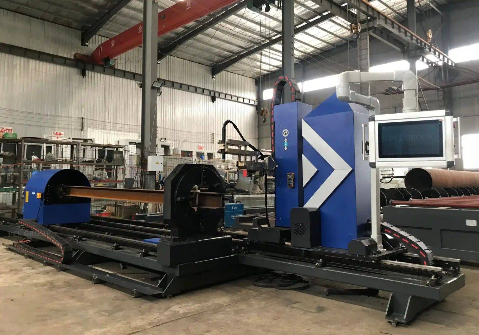
Structural members such as H-beams, I-beams, and bulb flats form the skeleton of any vessel. Traditional methods of cutting these profiles involved manual layout and oxy-fuel torches, which are labor-intensive and prone to human error. Integrated plasma profile cutting lines have revolutionized this workflow. A key focus for industrial engineers in this domain is the implementation of low maintenance systems designed for 24/7 operation in abrasive shipyard environments.
Reliability in H-beam processing is achieved through specialized engineering features. Hardened linear guides, shielded bellows for lead screws, and sophisticated dust extraction systems prevent the accumulation of metallic swarf and slag—byproducts that typically degrade machine components. Furthermore, the use of liquid-cooled torches extends the life of consumables, reducing the frequency of downtime for maintenance interventions. By selecting a plasma system with a high duty cycle and robust component protection, shipyards can maintain a continuous flow of structural members to the assembly jigs.
Multi-Axis Beveling for Weld Preparation
One of the most significant bottlenecks in shipbuilding is the preparation of plate edges for high-strength welds. Plasma systems equipped with 5-axis or 6-axis beveling heads allow for the simultaneous cutting and chamfering of plates. This capability covers a variety of profiles, including V, Y, X, and K-cuts, which are essential for full-penetration joints in thick hull plating.
The industrial engineering advantage here is the elimination of secondary grinding operations. A precise plasma bevel provides a clean, weld-ready surface that meets the stringent requirements of maritime classification societies. Advanced height control sensors, often using initial height sensing (IHS) and voltage feedback, ensure the torch maintains a constant distance from the plate, even if the material has slight undulations. This consistency is vital for maintaining a uniform bevel angle across the entire length of a 12-meter plate.
Maximizing Throughput with Offline Programming (OLP)
The hardware’s potential is only fully realized when coupled with offline programming. In a traditional setup, the machine remains idle while the operator manually inputs coordinates or adjusts nests at the controller. OLP moves this entire cognitive process to the engineering office. By utilizing the 3D models generated in ship design software (such as AVEVA or ShipConstructor), OLP software can automatically generate optimized toolpaths, nesting patterns, and lead-in/lead-out strategies.
OLP provides several strategic advantages:
1. Collision Avoidance and Simulation
Before the first spark is struck, the entire cutting sequence is simulated in a virtual environment. This identifies potential collisions between the torch head and tipped parts or plate skeletons, preventing costly equipment damage and unplanned downtime.
2. Material Utilization and Nesting
Shipbuilding involves expensive materials. OLP algorithms can nest complex hull shapes with a density that far exceeds manual capabilities. Features such as common-line cutting and bridge cutting reduce the number of pierces, extending consumable life and saving material.
3. Management of Thermal Distortion
Sophisticated OLP software allows engineers to dictate the cutting sequence to manage heat distribution across the plate. By strategically jumping between different areas of the nest, the software prevents the plate from “walking” or warping due to localized heat buildup, thereby preserving the dimensional accuracy of the parts.
Technical Conclusion on System Integration
For the industrial engineer, the implementation of a plasma cutting solution in a shipyard is an exercise in systems integration. It is not enough to have a fast torch; the machine must be an extension of the digital design office. The synchronization of offline programming with high-precision gantry motion ensures that every cut contributes to a streamlined assembly process. By focusing on the reliability of H-beam lines and the precision of multi-axis beveling, shipyards can mitigate the risks of structural misalignment and excessive labor costs.
In summary, the transition to automated plasma cutting represents a shift toward data-driven manufacturing. The ability to produce parts with high intersection accuracy and ready-to-weld edges directly impacts the shipyard’s bottom line. As vessels become more complex and delivery schedules more aggressive, the role of specialized plasma technology and its associated digital workflows becomes the cornerstone of modern maritime production efficiency.
-


LT240S tube laser cutting machine
-
LT120S tube laser cutting machine
-
Sale

Tank Fillet Welding Machine
Original price was: $1,000.00.$900.00Current price is: $900.00. -
Sale

MAK100 tube laser cutting machine
Original price was: $5,500.00.$5,000.00Current price is: $5,000.00. -

portable plasma air cutting machine
$1,200.00 -

2in1 fiber laser cutting machine
-

Air cooling Laser welding machine
-

HF h beam laser cutting machine
-

LT240 laser cutting machine
-

Laser welding machine
-


Cobot Welding Station
-

Gantry welding robot solution
-

Tracked Wheeled AGV Welding robot
-

LFH6020 Fiber laser cutting machine
-
LFP6020
-

robotic welidng machine
Advanced Fiber Laser Tube Processing Technology
Our CNC Fiber Laser Tube Cutting systems revolutionize metal fabrication by integrating high-precision cutting, punching, and profiling into a single automated workflow. Designed for versatility, this technology handles a wide array of profiles including Round, Square, Rectangular, and Oval tubes, as well as complex L-shaped and U-shaped channels.
- Precision Punching: High-speed hole punching with micron-level accuracy, eliminating the need for mechanical drilling or die-stamping.
- Complex Profiling: Advanced 3D pathing allows for intricate interlocking joints and specialized notch cuts, ideal for structural frames.
- High Material Efficiency: Intelligent nesting software minimizes scrap, reducing raw material costs across large production runs.
- Clean Finish: Delivers oxide-free, burr-free edges that require zero secondary grinding before welding.

Seamlessly processing multiple profiles with consistent precision.
Global Delivery & Logistics



From our high-tech manufacturing facility directly to your global site. PCL WeldCut ensures secure packaging, professional handling, and reliable international logistics to safeguard your equipment throughout the entire journey.