Precision Engineering in Pressure Vessel Fabrication
The manufacturing of pressure vessels—ranging from heat exchangers to storage tanks and reactors—is governed by strict regulatory codes such as ASME Section VIII. These standards mandate rigorous precision in material preparation to ensure structural integrity under extreme internal pressures. Historically, the preparation of vessel shells and heads involved manual layout and cutting, followed by extensive grinding to achieve the necessary bevel angles for welding. The introduction of 5-axis plasma beveling has transformed this workflow by integrating high-definition plasma technology with multi-axis CNC kinematics.
Mechanical Kinematics of 5-Axis Beveling
A 5-axis plasma head operates on a sophisticated coordinate system that extends beyond the standard X, Y, and Z axes. By incorporating two additional rotational axes—often referred to as the A and B axes—the system gains the ability to tilt the plasma torch in real-time. This tilt capability is essential for creating complex bevel profiles, including V, X, Y, and K cuts, which are standard in heavy-duty weld preparations.
The engineering challenge lies in maintaining the “Tool Center Point” (TCP) during rotation. When the torch tilts, the focal point of the plasma arc must remain precisely aligned with the programmed cutting path. Advanced CNC controllers use inverse kinematics to adjust the X, Y, and Z positions simultaneously as the head rotates. This synchronization ensures that the bevel angle remains consistent even when navigating the curved surfaces of a cylindrical vessel shell or a dished head.
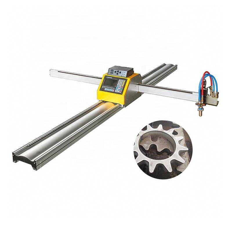
Achieving Superior Intersection Accuracy
One of the most demanding tasks in pressure vessel production is the cutting of nozzle openings and manways. These intersections are rarely simple circular holes; when a nozzle meets a cylindrical shell at an angle or offset, the resulting intersection line is a complex 3D curve. Standard 3-axis cutting cannot provide the necessary edge preparation for these openings, as the weld prep angle must vary continuously around the perimeter to maintain a constant root gap for the joining process.
The intersection accuracy provided by modern 5-axis plasma systems relies on integrated CAD/CAM software that calculates the exact geometry of the penetration. The plasma arc is adjusted dynamically to ensure the bevel angle compensates for the curvature of the shell. This level of precision eliminates the “fit-up” issues common in manual fabrication, where large gaps often require expensive and time-consuming “buttering” with weld metal before the structural pass can begin.
Structural Integrity and H-Beam Frame Design
The foundation of a Plasma Cutting Machine dictates its long-term accuracy and reliability. In industrial environments where heavy plates (ranging from 12mm to over 50mm) are processed, the machine frame must withstand significant thermal and mechanical stresses. Industrial engineers favor a low maintenance H-beam construction for the gantry and rails for several reasons.
First, the H-beam provides a superior strength-to-weight ratio, ensuring that the gantry remains rigid during high-speed directional changes. Rigidity is the primary defense against vibration. Any oscillation in the plasma head translates directly into “chatter” marks on the cut surface, which can compromise the metallurgical quality of the edge and necessitate secondary grinding.
Second, the thermal stability of heavy H-beam sections is critical. Plasma cutting generates localized heat; while the water table or downdraft system manages much of this, the machine frame must resist warping over thousands of duty cycles. H-beam structures allow for more robust mounting of linear guides and rack-and-pinion systems, leading to a longer mean time between service intervals. By reducing the frequency of rail realignments and mechanical calibrations, facilities can maintain a higher OEE (Overall Equipment Effectiveness).
Optimizing Throughput through Automated Weld Prep
In a traditional fabrication shop, the plasma machine is used only for “blanking” or cutting the initial shape. The plate is then moved to a separate station where workers use handheld grinders or bevellers to prepare the edges. This movement of material is a significant “waste” in Lean manufacturing terms.
A 5-axis plasma system performs the blanking and the beveling in a single setup. By automating pressure vessel fabrication, the total cycle time per component is reduced by 40% to 60%. Furthermore, the consistency of the plasma arc ensures that the Heat Affected Zone (HAZ) is minimized through high-speed travel, preserving the base metal’s mechanical properties.
Modern plasma power sources feature “True Hole” technology and rapid-response Torch Height Control (THC). THC is particularly vital when cutting vessel heads or large plates that may have slight surface deviations. By maintaining a constant voltage—and thus a constant distance between the nozzle and the workpiece—the system ensures that the kerf width remains uniform. This uniformity is the secret to achieving tight tolerances in the final vessel assembly.
Maintenance Considerations for Heavy-Duty Plasma Systems
From an industrial engineering perspective, the lifecycle cost of a plasma system is as important as its initial accuracy. The choice of H-beam construction and high-grade linear components directly impacts the maintenance schedule. Unlike lighter, sheet-metal based frames, heavy structural frames resist the “dents and dings” of a busy shop floor where overhead cranes are constantly moving multi-ton plates.
Maintenance teams focus on the consumable life of the plasma torch. Five-axis heads require precise alignment of the torch leads to prevent twisting and fatigue during the complex rotations of the A and B axes. High-end systems utilize specialized cable management chains and “limitless” rotation joints to prevent downtime caused by cable failure. When combined with a stable H-beam base, the mechanical wear on drive motors and gearboxes is significantly reduced, as the system does not have to constantly fight against frame flex or misalignment.
Conclusion on Industrial Implementation
The implementation of a 5-axis plasma cutting system represents a strategic shift from labor-intensive fabrication to capital-intensive precision engineering. For the pressure vessel industry, where the cost of a single weld failure can be catastrophic, the ability to produce perfectly beveled intersections and repeatable geometries is invaluable. By selecting machines characterized by rigid H-beam structures and sophisticated 5-axis kinematics, manufacturers ensure high intersection accuracy and low maintenance requirements, ultimately securing a more competitive position in the global heavy fabrication market.
-


LT240S tube laser cutting machine
-
LT120S tube laser cutting machine
-
Sale

Tank Fillet Welding Machine
Original price was: $1,000.00.$900.00Current price is: $900.00. -
Sale

MAK100 tube laser cutting machine
Original price was: $5,500.00.$5,000.00Current price is: $5,000.00. -

portable plasma air cutting machine
$1,200.00 -

2in1 fiber laser cutting machine
-

Air cooling Laser welding machine
-

HF h beam laser cutting machine
-

LT240 laser cutting machine
-

Laser welding machine
-


Cobot Welding Station
-

Gantry welding robot solution
-

Tracked Wheeled AGV Welding robot
-

LFH6020 Fiber laser cutting machine
-
LFP6020
-

robotic welidng machine
Advanced Fiber Laser Tube Processing Technology
Our CNC Fiber Laser Tube Cutting systems revolutionize metal fabrication by integrating high-precision cutting, punching, and profiling into a single automated workflow. Designed for versatility, this technology handles a wide array of profiles including Round, Square, Rectangular, and Oval tubes, as well as complex L-shaped and U-shaped channels.
- Precision Punching: High-speed hole punching with micron-level accuracy, eliminating the need for mechanical drilling or die-stamping.
- Complex Profiling: Advanced 3D pathing allows for intricate interlocking joints and specialized notch cuts, ideal for structural frames.
- High Material Efficiency: Intelligent nesting software minimizes scrap, reducing raw material costs across large production runs.
- Clean Finish: Delivers oxide-free, burr-free edges that require zero secondary grinding before welding.

Seamlessly processing multiple profiles with consistent precision.
Global Delivery & Logistics



From our high-tech manufacturing facility directly to your global site. PCL WeldCut ensures secure packaging, professional handling, and reliable international logistics to safeguard your equipment throughout the entire journey.
One thought on “Plasma Cutting Machine with 5-Axis Beveling for for Pressure Vessels”
The PCL Laser exceeded our expectations in terms of speed and stability.